In this post I’ll discuss how I setup and render terrain mesh in the OpenGL terrain rendering demo. Most of the relevant code for this is in the ter-terrain.cpp file.
Setting up a grid of vertices
Unless you know how to use a 3D modeling program properly, a reasonable way to create a decent mesh for a terrain consists in using a grid of vertices and elevate them according to a height map image. In order to create the grid we only need to decide how many rows and columns we want. This, in the end, determines the number of polygons and the resolution of the terrain.
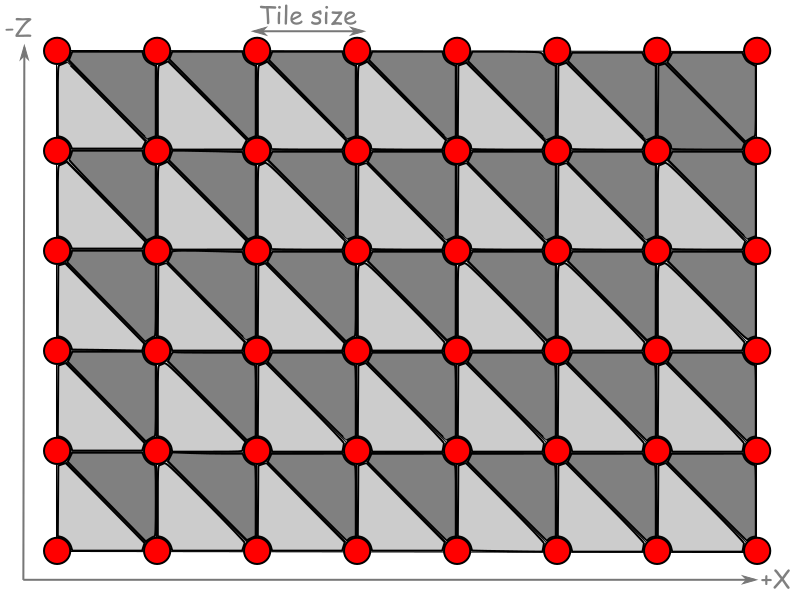
We need to map these vertices to world coordinates too. We do that by defining a tile size, which is the distance between consecutive vertices in world units. Larger tile sizes increase the size of the terrain but lower the resolution by creating larger polygons.
The image below shows an 8×6 grid that defines 35 tiles. Each tile is rendered using 2 triangles:
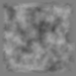
The next step is to elevate these vertices so we don’t end up with a boring flat surface. We do this by sampling the height map image for each vertex in the grid. A height map is a gray scale image where the values of the pixels represent altitudes at different positions. The closer the color is to white, the more elevated it is.
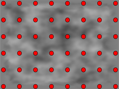
Adding more vertices to the grid increases the number of sampling points from the height map and reduces the sampling distances, leading to a smoother and more precise representation of the height map in the resulting terrain.
Of course, we still need to map the height map samples (gray scale colors) to altitudes in world units. In the demo I do this by normalizing the color values to [-1,+1] and then applying a scale factor to compute the altitude values in world space. By playing with the scaling factor we can make our terrain look more or less abrupt.
 |
 |
For reference, the height map sampling is implemented in ter_terrain_set_heights_from_texture().
Creating the mesh
At this point we know the full position (x, y, z) in world coordinates of all the vertices in our grid. The next step is to build the actual triangle mesh that we will use to render the terrain and the normal vectors for each triangle. This process is described below and is implemented in the ter_terrain_build_mesh() function.
Computing normals
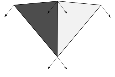
In order to get nice lighting on our terrain we need to compute normals for each vertex in the mesh. A simple way to achieve this is would be to compute the normal for each face (triangle) and use that normal for each vertex in the triangle. This works, but it has 3 problems:
1. Every vertex of each triangle has the same exact normal, which leads to a rather flat result.
2. Adjacent triangles with different orientations showcase abrupt changes in the normal value, leading to significantly different lighting across the surfaces that highlight the individual triangles in the mesh.
3. Because each vertex in the mesh can have a different normal value for each triangle it participates in, we need to replicate the vertices when we render, which is not optimal.
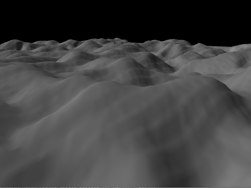
Alternatively, we can compute the normals for each vertex considering the heights of its neighboring vertices. This solves all the problems mentioned above and leads to much better results thanks to the interpolation of the normal vectors across the triangles, which leads to smooth lighting reflection transitions:
 |
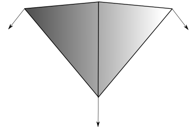 |
The implementation for this is in the function calculate_normal(), which takes the column and row indices of the vertex in the grid and calculates the Y coordinate by sampling the heights of the 4 nearby vertices in the grid.
Preparing the draw call
Now that we know the positions of all the vertices and their normal vectors we have all the information that we need to render the terrain. We still have to decide how exactly we want to render all the polygons.
The simplest way to render the terrain using a single draw call is to setup a vertex buffer with data for each triangle in the mesh (including position and normal information) and use GL_TRIANGLES for the primitive of the draw call. This, however, is not the best option from the point of view of performance.
Because the terrain will typically contain a large number of vertices and most of them participate in multiple triangles, we end up uploading a large amount of vertex data to the GPU and processing a lot of vertices in the draw call. The result is large memory requirements and suboptimal performance.
For reference, the terrain I used in the demo from my original post used a 251×251 grid. This grid represents 250×250 tiles, each one rendered as two triangles (6 vertices/tile), so we end up with 250x250x6=375,000 vertices. For each of these vertices we need to upload 24 bytes of vertex data with the position and normal, so we end up with a GPU buffer that is almost 9MB large.
One obvious way to reduce this is to render the terrain using triangle strips. The problem with this is that in theory, we can’t render the terrain with just one strip, we would need one strip (and so, one draw call) per tile column or one strip per tile row. Fortunately, we can use degenerate triangles to link separate strips for each column into a single draw call. With this we trim down the number of vertices to 126,000 and the size of the buffer to a bit below 3 MB. This alone produced a 15%-20% performance increase in the demo.
We can do better though. A lot of the vertices in the terrain mesh participate in various triangles across the large triangle strip in the draw call, so we can reduce memory requirements by using an index buffer to render the strip. If we do this, we trim things down to 63,000 vertices and ~1.5MB. This added another 4%-5% performance bonus over the original implementation.
Clipping
So far we have been rendering the full mesh of the terrain in each frame and we do this by uploading the vertex data to the GPU just once (for example in the first frame). However, depending on where the camera is located and where it is looking at, just a fraction of the terrain may be visible.
Although the GPU will discard all the geometry and fragments that fall outside the viewport, it still has to process each vertex in the vertex shader stage before it can clip non-visible triangles. Because the number of triangles in the terrain is large, this is suboptimal and to address this we want to do CPU-side clipping before we render.
Doing CPU-side clippig comes with some additional complexities though: it requires that we compute the visible region of the terrain and upload new vertex data to the GPU in each frame preventin GPU stalls.
In the demo, we implement the clipping by computing a quad sub-region of the terrain that includes the visible area that we need to render. Once we know the sub-region that we want to render, we compute the new indices of the vertices that participate in the region so we can render it using a single triangle strip. Finally, we upload the new index data to the index buffer for use in the follow-up draw call.
Avoiding GPU stalls
Although all the above is correct, it actually leads, as described, to much worse performance in general. The reason for this is that our uploads of vertex data in each frame lead to frequent GPU stalls. This happens in two scenarios:
1. In the same frame, because we need to upload different vertex data for the rendering of the terrain for the shadow map and the scene (the shadow map renders the terrain from the point of view of the light, so the visible region of the terrain is different). This creates stalls because the rendering of the terrain for the shadow map might not have completed before we attempt to upload new data to the index buffer in order to render the terrain for the scene.
2. Between different frames. Because the GPU might not be completely done rendering the previous frame (and thus, stills needs the index buffer data available) before we start preparing the next frame and attempt to upload new terrain index data for it.
In the case of the Intel Mesa driver, these GPU stalls can be easily identified by using the environment variable INTEL_DEBUG=perf. When using this, the driver will detect these situations and produce warnings informing about the stalls, the buffers affected and the regions of the buffers that generate the stall, such as:
Stalling on glBufferSubData(0, 503992) (492kb) to a busy (0-1007984)
buffer object.  Use glMapBufferRange() to avoid this.
The solution to this problem that I implemented (other than trying to put as much work as possible between read/write accesses to the index buffer) comes in two forms:
1. Circular buffers
In this case, we allocate a larger buffer than we need so that each subsequent upload of new index data happens in a separate sub-region of the allocated buffer. I set up the demo so that each circular buffer is large enough to hold the index data required for all updates of the index buffer happening in each frame (the shadow map and the scene).
2. Multi-buffering
We allocate more than one circular buffer. When we don’t have enough free space at the end of the current buffer to upload the new index buffer data, we upload it to a different circular buffer instead. When we run out of buffers we circle back to the first one (which at this point will hopefully be free to be re-used again).
So why not just use a single, very large circular buffer? Mostly because there are limits to the size of the buffers that the GPU may be able to handle correctly (or efficiently). Also, why not having many smaller independent buffers instead of circular buffers? That would work just fine, but using fewer, larger buffers reduces the number of objects we need to bind/unbind and is better to prevent memory fragmentation, so that’s a plus.
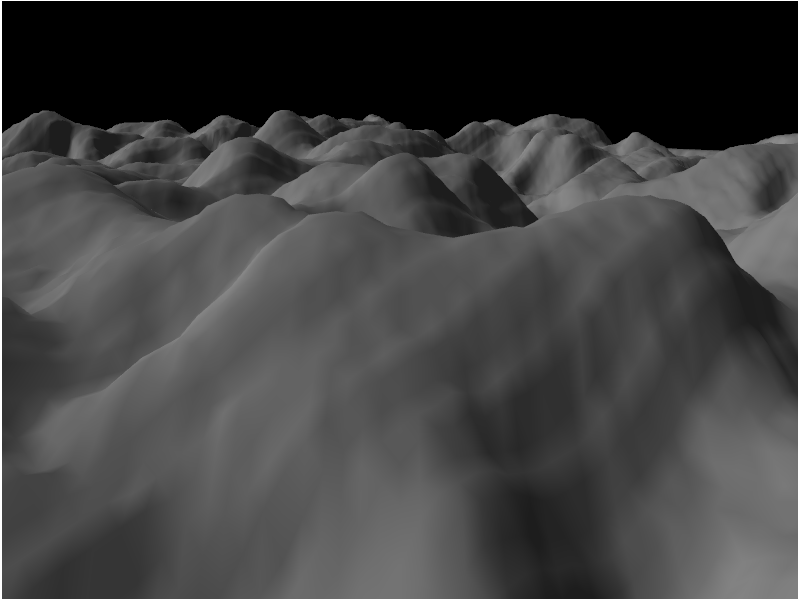
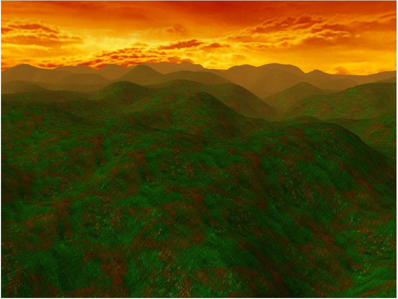
Final touches
We are almost done, at this point we only need to add a texture to the terrain surface, add some slight fog effect for distant pixels to create a more realistic look, add a skybox (it is important to choose the color of the fog so it matches the color of the sky!) and tweak the lighting parameters to get a nice result:
I hope to cover some of these aspects in future posts, so stay tuned for more!
Really nice explanation!