In the previous post in this series I introduced how to render the shadow map image, which is simply the depth information for the scene from the view point of the light. In this post I will cover how to use the shadow map to render shadows.
The general idea is that for each fragment we produce we compute the light space position of the fragment. In this space, the Z component tells us the depth of the fragment from the perspective of the light source. The next step requires to compare this value with the shadow map value for that same X,Y position. If the fragment’s light space Z is larger than the value we read from the shadow map, then it means that this fragment is behind an object that is closer to the light and therefore we can say that it is in the shadows, otherwise we know it receives direct light.
Changes in the shader code
Let’s have a look at the vertex shader changes required for this:
void main()
{
   vec4 pos = vec4(in_position.x, in_position.y, in_position.z, 1.0);
   out_world_pos = Model * pos;
   gl_Position = Projection * View * out_world_pos;

   [...]

   out_light_space_pos = LightViewProjection * out_world_pos;
}
The vertex shader code above only shows the code relevant to the shadow mapping technique. Model is the model matrix with the spatial transforms for the vertex we are rendering, View and Projection represent the camera’s view and projection matrices and the LightViewProjection represents the product of the light’s view and projection matrices. The variables prefixed with ‘out’ represent vertex shader outputs to the fragment shader.
The code generates the world space position of the vertex (world_pos) and clip space position (gl_Position) as usual, but then also computes the light space position for the vertex (out_light_space_pos) by applying the View and Projection transforms of the light to the world position of the vertex, which gives us the position of the vertex in light space. This will be used in the fragment shader to sample the shadow map.
The fragment shader will need to:
- Apply perspective division to compute NDC coordinates from the interpolated light space position of the fragment. Notice that this process is slightly different between OpenGL and Vulkan, since Vulkan’s NDC Z is expected to be in the range [0, 1] instead of OpenGL’s [-1, 1].
-
Transform the X,Y coordinates from NDC space [-1, 1] to texture space [0, 1].
-
Sample the shadow map and compare the result with the light space Z position we computed for this fragment to decide if the fragment is shadowed.
The implementation would look something like this:
float
compute_shadow_factor(vec4 light_space_pos, sampler2D shadow_map)
{
   // Convert light space position to NDC
   vec3 light_space_ndc = light_space_pos.xyz /= light_space_pos.w;

   // If the fragment is outside the light's projection then it is outside
   // the light's influence, which means it is in the shadow (notice that
   // such sample would be outside the shadow map image)
   if (abs(light_space_ndc.x) > 1.0 ||
       abs(light_space_ndc.y) > 1.0 ||
       abs(light_space_ndc.z) > 1.0)
      return 0.0;

   // Translate from NDC to shadow map space (Vulkan's Z is already in [0..1])
   vec2 shadow_map_coord = light_space_ndc.xy * 0.5 + 0.5;

   // Check if the sample is in the light or in the shadow
   if (light_space_ndc.z > texture(shadow_map, shadow_map_coord.xy).x)
      return 0.0; // In the shadow

   // In the light
   return 1.0;
}
The function returns 0.0 if the fragment is in the shadows and 1.0 otherwise. Note that the function also avoids sampling the shadow map for fragments that are outside the light’s frustum (and therefore are not recorded in the shadow map texture): we know that any fragment in this situation is shadowed because it is obviously not visible from the light. This assumption is valid for spotlights and point lights because in these cases the shadow map captures the entire influence area of the light source, for directional lights that affect the entire scene however, we usually need to limit the light’s frustum to the surroundings of the camera, and in that case we probably want want to consider fragments outside the frustum as lighted instead.
Now all that remains in the shader code is to use this factor to eliminate the diffuse and specular components for fragments that are in the shadows. To achieve this we can simply multiply these components by the factor computed by this function.
Changes in the program
The list of changes in the main program are straight forward: we only need to update the pipeline layout and descriptors to attach the new resources required by the shaders, specifically, the light’s view projection matrix in the vertex shader (which could be bound as a push constant buffer or a uniform buffer for example) and the shadow map sampler in the fragment shader.
Binding the light’s ViewProjection matrix is no different from binding the other matrices we need in the shaders so I won’t cover it here. The shadow map sampler doesn’t really have any mysteries either, but since that is new let’s have a look at the code:
...
VkSampler sampler;
VkSamplerCreateInfo sampler_info = {};
sampler_info.sType = VK_STRUCTURE_TYPE_SAMPLER_CREATE_INFO;
sampler_info.addressModeU = VK_SAMPLER_ADDRESS_MODE_CLAMP_TO_EDGE;
sampler_info.addressModeV = VK_SAMPLER_ADDRESS_MODE_CLAMP_TO_EDGE;
sampler_info.addressModeW = VK_SAMPLER_ADDRESS_MODE_CLAMP_TO_EDGE;
sampler_info.anisotropyEnable = false;
sampler_info.maxAnisotropy = 1.0f;
sampler_info.borderColor = VK_BORDER_COLOR_INT_OPAQUE_BLACK;
sampler_info.unnormalizedCoordinates = false;
sampler_info.compareEnable = false;
sampler_info.compareOp = VK_COMPARE_OP_ALWAYS;
sampler_info.magFilter = VK_FILTER_LINEAR;
sampler_info.minFilter = VK_FILTER_LINEAR;
sampler_info.mipmapMode = VK_SAMPLER_MIPMAP_MODE_NEAREST;
sampler_info.mipLodBias = 0.0f;
sampler_info.minLod = 0.0f;
sampler_info.maxLod = 100.0f;

VkResult result =
   vkCreateSampler(device, &sampler_info, NULL, &sampler);
...
This creates the sampler object that we will use to sample the shadow map image. The address mode fields are not very relevant since our shader ensures that we do not attempt to sample outside the shadow map, we use linear filtering, but that is not mandatory of course, and we select nearest for the mipmap filter because we don’t have more than one miplevel in the shadow map.
Next we have to bind this sampler to the actual shadow map image. As usual in Vulkan, we do this with a descriptor update. For that we need to create a descriptor of type VK_DESCRIPTOR_TYPE_COMBINED_IMAGE_SAMPLER, and then do the update like this:
VkDescriptorImageInfo image_info;
image_info.sampler = sampler;
image_info.imageView = shadow_map_view;
image_info.imageLayout = VK_IMAGE_LAYOUT_SHADER_READ_ONLY_OPTIMAL;

VkWriteDescriptorSet writes;
writes.sType = VK_STRUCTURE_TYPE_WRITE_DESCRIPTOR_SET;
writes.pNext = NULL;
writes.dstSet = image_descriptor_set;
writes.dstBinding = 0;
writes.dstArrayElement = 0;
writes.descriptorCount = 1;
writes.descriptorType = VK_DESCRIPTOR_TYPE_COMBINED_IMAGE_SAMPLER;
writes.pBufferInfo = NULL;
writes.pImageInfo = &image_info;
writes.pTexelBufferView = NULL;

vkUpdateDescriptorSets(ctx->device, 1, &writes, 0, NULL);
A combined image sampler brings together the texture image to sample from (a VkImageView of the image actually) and the description of the filtering we want to use to sample that image (a VkSampler). As with all descriptor sets, we need to indicate its binding point in the set (in our case it is 0 because we have a separate descriptor set layout for this that only contains one binding for the combined image sampler).
Notice that we need to specify the layout of the image when it will be sampled from the shaders, which needs to be VK_IMAGE_LAYOUT_SHADER_READ_ONLY_OPTIMAL.
If you revisit the definition of our render pass for the shadow map image, you’ll see that we had it automatically transition the shadow map to this layout at the end of the render pass, so we know the shadow map image will be in this layout immediately after it has been rendered, so we don’t need to add barriers to execute the layout transition manually.
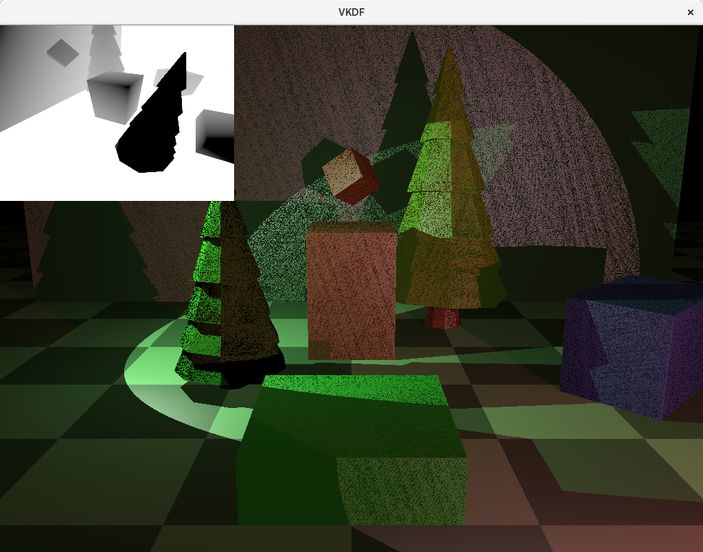
So that’s it, with this we have all the pieces and our scene should be rendering shadows now. Unfortunately, we are not quite done yet, if you look at the results, you will notice a lot of dark noise in surfaces that are directly lit. This is an artifact of shadow mapping called self-shadowing or shadow acne. The next section explains how to get rid of it.
Eliminating self-shadowing
Self-shadowing can happen for fragments on surfaces that are directly lit by a source light for which we are producing a shadow map. The reason for this is that these are the fragments’s Z coordinate in light space should exactly match the value we read from the shadow map for the same X,Y coordinates. In other words, for these fragments we expect:
light_space_ndc.z == texture(shadow_map, shadow_map_coord.xy).x.
However, due to different precession errors that can be generated on both sides of that equation, we may end up with slightly different values for each side and when the value we produce for light_space_ndc.z end ups being larger than what we read from the shadow map, even if it is a very small amount, it will mark the pixel as shadowed, leading to the result we see in that image.
The usual way to fix this problem involves adding a small depth offset or bias to the depth values we store in the shadow map so we ensure that we always read a larger value from the shadow map for the fragment. Another way to think about this is to think that when we record the shadow map, we push every object in the scene slightly away from the light source. Unfortunately, this depth offset bias should not be a constant value, since the angle between the surface normals and the vectors from the light source to the fragments also affects the bias value that we should use to correct the self-shadowing.
Thankfully, GPU hardware provides means to account for this. In Vulkan, when we define the rasterization state of the pipeline we use to create the shadow map, we can add the following:
VkPipelineRasterizationStateCreateInfo rs;
...
rs.depthBiasEnable = VK_TRUE;
rs.depthBiasConstantFactor = 4.0f;
rs.depthBiasSlopeFactor = 1.5f;
Where depthBiasConstantFactor is a constant factor that is automatically added to all depth values produced and depthBiasSlopeFactor is a factor that is used to compute depth offsets also based on the angle. This provides us with the means we need without having to do any extra work in the shaders ourselves to offset the depth values correctly. In OpenGL the same functionality is available via glPolygonOffset().
Notice that the bias values that need to be used to obtain the best results can change for each scene. Also, notice that too big values can lead to shadows that are “detached” from the objects that cast them leading to very unrealistic results. This effect is also known as Peter Panning, and can be observed in this image:
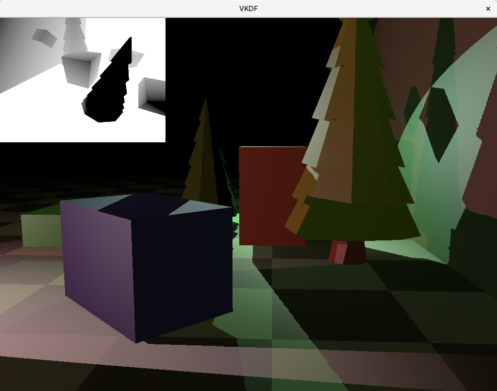
As we can see in the image, we no longer have self-shadowing, but now we have the opposite problem: the shadows casted by the red and blue blocks are visibly incorrect, as if they were being rendered further away from the light source than they should be.
If the bias values are chosen carefully, then we should be able to get a good result, although some times we might need to accept some level of visible self-shadowing or visible Peter Panning:
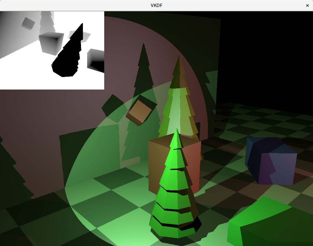
The image above shows correct shadowing without any self-shadowing or visible Peter Panning. You may wonder why we can’t see some of the shadows from the red light in the floor where the green light is more intense. The reason is that even though it is not clear because I don’t actually render the objects projecting the lights, the green light is mostly looking down, so its reflection on the floor (that has normals pointing upwards) is strong enough that the contribution from the red light to the floor pixels in this area is insignificant in comparison making the shadows casted from the red light barely visible. You can still see some shadowing if you get close enough with the camera though, I promise 😉
Shadow antialiasing
The images above show aliasing around at the edges of the shadows. This happens because for each fragment we decide if it is shadowed or not as a boolean decision, and we use that result to fully shadow or fully light the pixel, leading to aliasing:
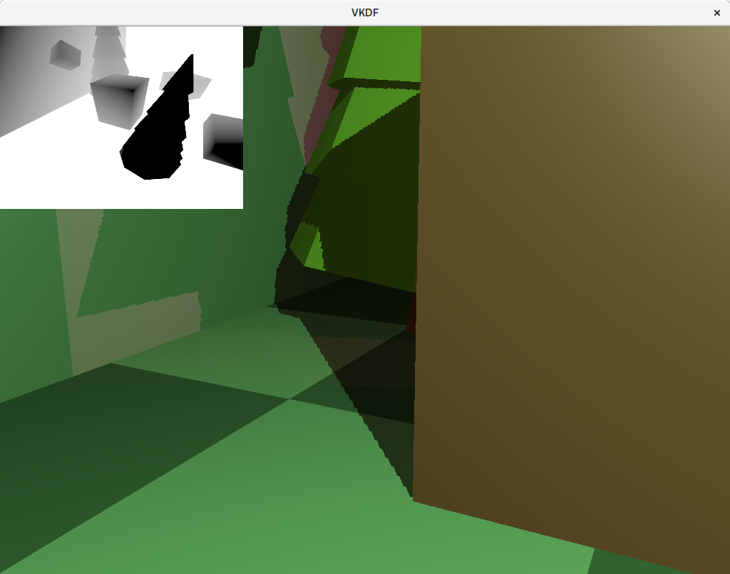
Another thing contributing to the aliasing effect is that a single pixel in the shadow map image can possibly expand to multiple pixels in camera space. That can happen if the camera is looking at an area of the scene that is close to the camera, but far away from the light source for example. In that case, the resolution of that area of the scene in the shadow map is small, but it is large for the camera, meaning that we end up sampling the same pixel from the shadow map to shadow larger areas in the scene as seen by the camera.
Increasing the resolution of the shadow map image will help with this, but it is not a very scalable solution and can quickly become prohibitive. Alternatively, we can implement something called Percentage-Closer Filtering to produce antialiased shadows. The technique is simple: instead of sampling just one texel from the shadow map, we take multiple samples in its neighborhood and average the results to produce shadow factors that do not need to be exactly 1 o 0, but can be somewhere in between, producing smoother transitions for shadowed pixels on the shadow edges. The more samples we take, the smoother the shadows edges get but do note that extra samples per pixel also come with a performance cost.
This is how we can update our compute_shadow_factor() function to add PCF:
float
compute_shadow_factor(vec4 light_space_pos,
                      sampler2D shadow_map,
                      uint shadow_map_size,
                      uint pcf_size)
{
   vec3 light_space_ndc = light_space_pos.xyz /= light_space_pos.w;

   if (abs(light_space_ndc.x) > 1.0 ||
       abs(light_space_ndc.y) > 1.0 ||
       abs(light_space_ndc.z) > 1.0)
      return 0.0;

   vec2 shadow_map_coord = light_space_ndc.xy * 0.5 + 0.5;

   // compute total number of samples to take from the shadow map
   int pcf_size_minus_1 = int(pcf_size - 1);
   float kernel_size = 2.0 * pcf_size_minus_1 + 1.0;
   float num_samples = kernel_size * kernel_size;

   // Counter for the shadow map samples not in the shadow
   float lighted_count = 0.0;

   // Take samples from the shadow map
   float shadow_map_texel_size = 1.0 / shadow_map_size;
   for (int x = -pcf_size_minus_1; x <= pcf_size_minus_1; x++)
   for (int y = -pcf_size_minus_1; y <= pcf_size_minus_1; y++) {
      // Compute coordinate for this PFC sample
      vec2 pcf_coord = shadow_map_coord + vec2(x, y) * shadow_map_texel_size;

      // Check if the sample is in light or in the shadow
      if (light_space_ndc.z <= texture(shadow_map, pcf_coord.xy).x)
         lighted_count += 1.0;
   }

   return lighted_count / num_samples;
}
We now have a loop where we go through the samples in the neighborhood of the texel and average their respective shadow factors. Notice that because we sample the shadow map in texture space [0, 1], we need to consider the size of the shadow map image to properly compute the coordinates for the texels in the neighborhood so the application needs to provide this for every shadow map.
Conclusion
In this post we discussed how to use the shadow map image to produce shadows in the scene as well as typical issues that can show up with the shadow mapping technique, such as self-shadowing and aliasing, and how to correct them. This will be the last post in this series, there is a lot more stuff to cover about lighting and shadowing, such as Cascaded Shadow Maps (which I introduced briefly in this other post), but I think (or I hope) that this series provides enough material to get anyone interested in the technique a reference for how to implement it.