Why don't we do a demo? Part 3: developing the user interfaces
In this instalment of the “Why don’t we do a demo?” series I’ll continue through the software development part of the demo and I’ll end up with an MVP that will be later shaped into a finished product. Check out the previous parts (The plan, Software development) to have more context on how we got here.
Problem 13: Bringing up the touch-display in the console device
I chose the display hardware based on what was readily supported in Zephyr so, in theory, I’m expecting it to work out of the box. However, things are rarely that simple.
There’s a basic LVGL sample as a starting point to check the hardware. In principle, if that works, all I have to do then is to design and implement the user interface. The sample works but, as the docs explain, I’ll need to do a small manual tweak in the board:
Touch controller IRQ line is not connected by default. You will need to solder the 5 INT jumper to use it. You will also need to adjust driver configuration and its Device Tree entry to make use of it.
Besides, while the basic sample works, there are other problems when I try to draw more complex layouts.
Solution
Soldering the jumper isn’t really an obstacle:
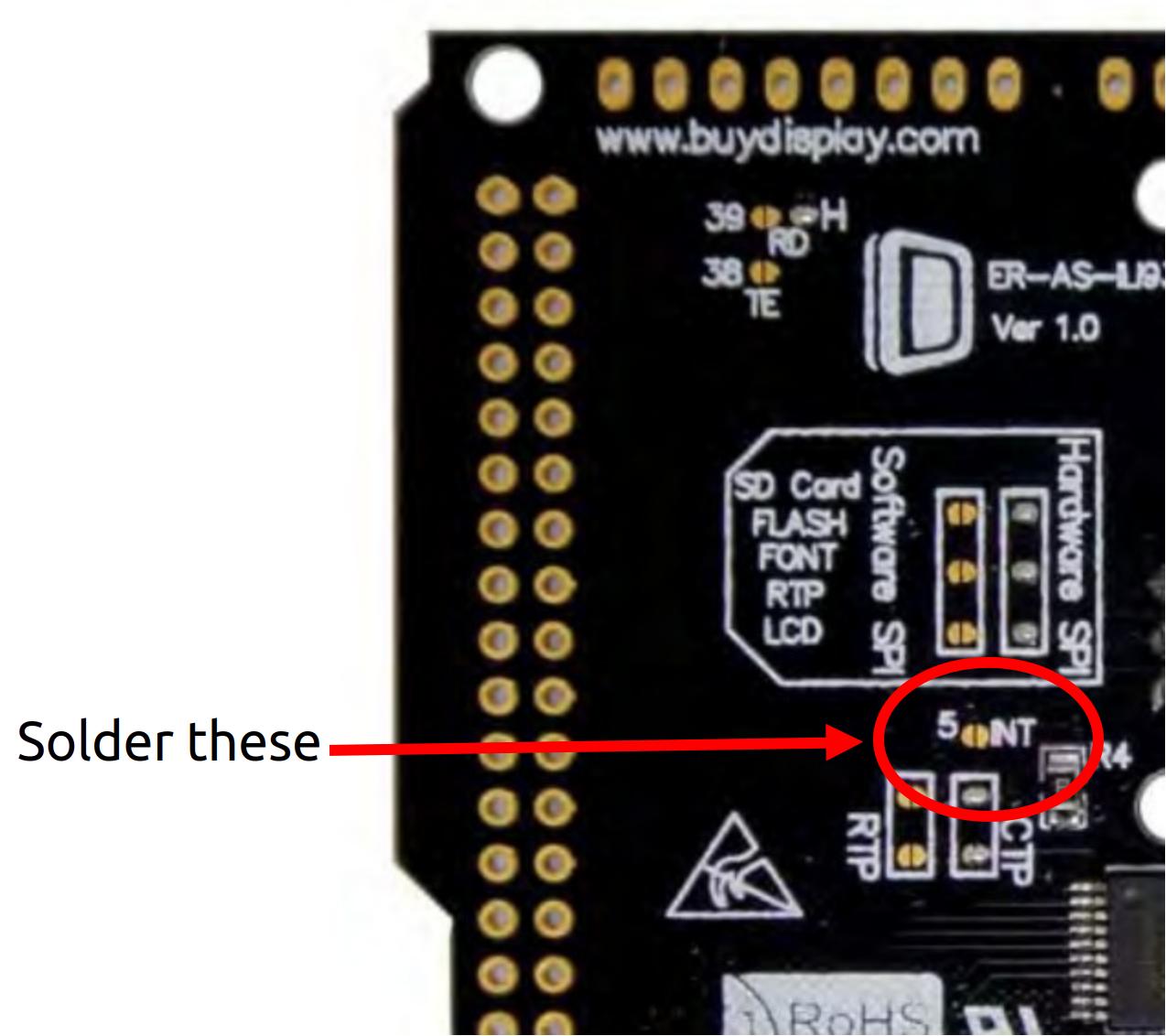
The pads are accessible and big enough to be easy to solder using a solder pen or silver paste syringe with a steady hand:

After soldering, I tested the sample application again and I could check that the touchscreen works by clicking on the test button:
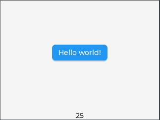
But now, if I continue building upon this, creating a proper interface with more widgets and a more complex layout, even if it’s just for testing for now, the display shows a blank screen.
This is a fairly common problem and it was easy to search for info
about it, everything pointed to the small default size of the memory
region for the LVGL heap (CONFIG_LV_Z_MEM_POOL_SIZE). After
some experiments I settled on a value that worked for the application
needs. To err on the safe side, the strategy is to allocate as much
memory as possible to LVGL after the memory needs of all the other
subsystems are met. The network stack and web server are the other parts
that need large-ish memory allocations, but the LVGL memory pool will be
the largest by far, at 32 KB.
Building the application with this configuration shows that I’m now using almost all the RAM:
Memory region         Used Size  Region Size  %age Used
           FLASH:      780028 B         1 MB     74.39%
             RAM:      251936 B       256 KB     96.11%
        IDT_LIST:          0 GB        32 KB      0.00%
But I can continue adding more widgets and creating more complex GUI layouts.
Problem 14: Touch-display problems
The initial LVGL “hello world” test above works as expected when tested on the display but, once I start adding more components to the interface, something seems wrong. Buttons aren’t pressed when I click on them, and touching random areas of the display trigger some widgets in other parts of the screen.
After a while, I noticed this behavior isn’t random. When I click something on the right side, the widget receiving the action is on the left side. When I click on the top area, the action is triggered at the bottom. The touch coordinates seem to be flipped. This probably went unnoticed because the layout of the “hello world” sample is just a single button in the center of the display, that is, it’s symmetrical in both axes, so any touch on the button will push it, flipped coordinates or not.
Solution
This one’s really easy, just a matter of removing the pointer axes inversion properties from the display device tree. Done and merged.
Problem 15: GUI design
The design and implementation of the graphical interface involves two different problems:
- How to fit all the information and controls in a tiny display and in a platform like this.
- How to implement it effectively.
In terms of design, I’m restricted by the screen real state (3.5 inches), but also by the hardware (memory and display speed). I certainly can’t make anything as responsive and feature-rich as what we’re used to in smartphones, so I need to keep it simple but functional.
With regards to implementation, the main obstacle is the complexity of the LVGL api and the amount of trial-and-error needed while tweaking and testing the layout, which can be very time-consuming, even when testing on the simulator. While LVGL isn’t more complex than other graphical libraries, the amount of widget configuration variables, particularly related to styling, means I’ll still need to do a lot of tests to get the positioning and behavior just right.
Solution
I started designing the simplest possible layout, a main container with subcontainers arranged in a single column, where every component is a widget box containing the controls for a peripheral slot. It’d look something like this:
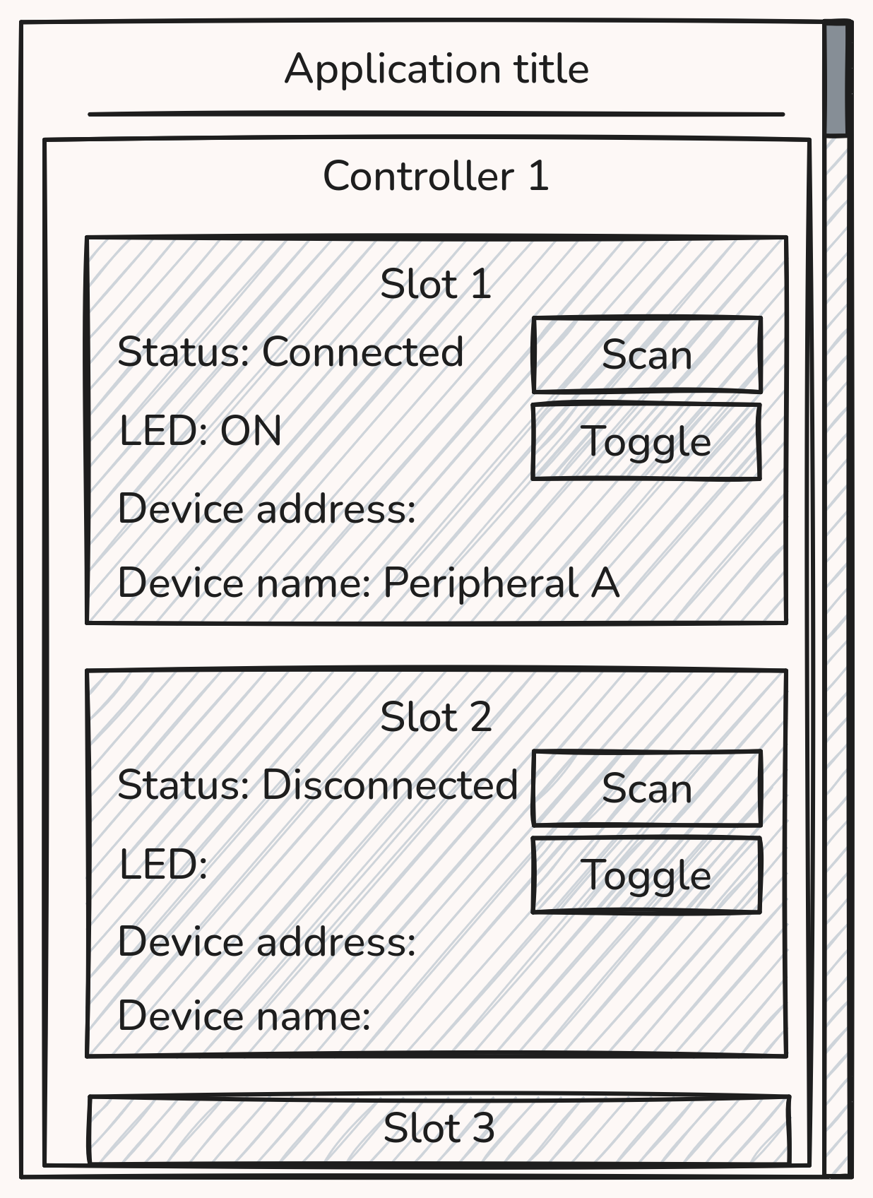
When a slot isn’t connected to any peripheral, I can make everything except for the “Status” label and the “Scan” button invisible, I can shrink the containers vertically. The scrollbar would let us move through the available slots if they don’t all fit in the main container.
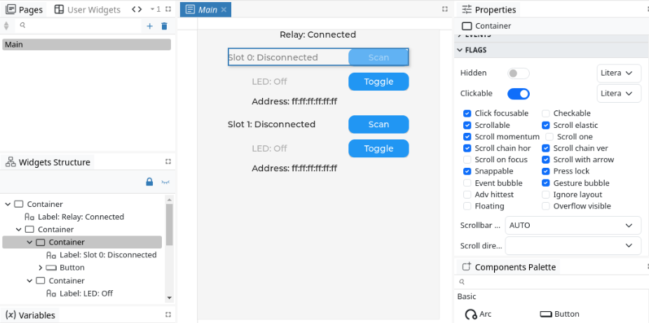
Now I need to grow the initial LVGL example code to implement this layout. Normally, this would involve a lot of iterations of changing details in the code, building and testing until I get everything looking and working the way I want. Fortunately, I found a tool (EEZ Studio) that’ll make part of the process much easier and faster, as it has an LVGL visual editor and code generator that will let me sketch the layout visually, do all the style changes and then generate the code. I’m not taking the generated code as is, as I need to integrate it into the application and I’ll want to do some things differently, but this is a huge time saver compared to doing the whole process by hand.
Problem 16: Display refresh speed
The GUI is looking good now, I can test it on the board and control the peripherals through the display, but I noticed that when the peripheral controls don’t fit into one screen and I need to scroll down to reach the additional controls, the scroll redisplay is really slow. Normally, re-drawing a label or a button happens fast enough, but re-drawing the whole screen happens too slowly, you can clearly notice parts of the screen being updated as you scroll, with the naked eye. This drags down the responsiveness and makes the display practicaly unusable in some scenarios.
All in all, this adds yet another restriction: no scrolling.
Solution
The best solution I could find for this is to draw a single controller widget container in the screen at a time, and switch from one controller to another using tabs. In each controller container, I also need to make sure all peripheral widgets fit in a single screen so I can safely disable and avoid scrolling altogether:
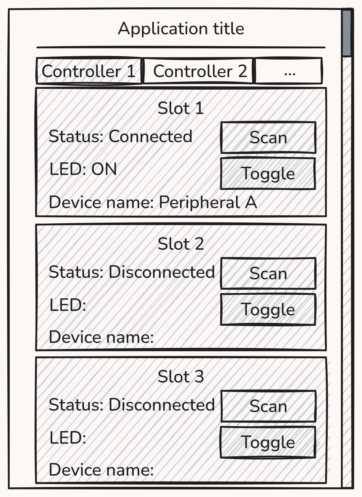
That’ll do, in theory. Implementing it isn’t too much of a hassle after having done the previous, non-tabbed version. The GUI logic is simple enough, and keeping a hierarchical and instance-based model for the data structures, where widgets are nested inside containers (nested within other containers), and certain parts can be modeled and duplicated, makes it easy to control each widget group and make them reactive to events. For instance, remove the peripheral widgets of a controller when the controller isn’t connected, or disable the “Scan” button while the scan is already ongoing.
void setup_slot(int r, int s)
{
    lv_obj_t *tab = controller_widgets[r].tab;
    struct slot_widget *slot = &controller_widgets[r].slots[s];
    lv_obj_t *label;

    slot->slot_idx = s;
    slot->controller_idx = r;

    slot->slot_cont = lv_obj_create(tab);
    [...]

    slot->slot_status_cont = lv_obj_create(slot->slot_cont);
    [...]

    slot->status_label = lv_label_create(slot->slot_status_cont);
    lv_obj_set_size(slot->status_label, LV_SIZE_CONTENT, LV_SIZE_CONTENT);
    lv_label_set_text_fmt(slot->status_label, "Slot %d: Disconnected", s + 1);
    slot->scan_btn = lv_btn_create(slot->slot_status_cont);
    label = lv_label_create(slot->scan_btn);
    lv_obj_set_size(label, LV_SIZE_CONTENT, LV_SIZE_CONTENT);
    lv_label_set_text(label, "Scan");
    lv_obj_add_event_cb(slot->scan_btn, controller_scan_btn_cb,
        LV_EVENT_CLICKED, (void *)slot);
    [...]
}

void setup_controller(int r)
{
    char controller_str[30];
    lv_obj_t *label_cont;
    lv_obj_t *label;
    lv_obj_t *tab;
    int i;

    snprintf(controller_str, sizeof(controller_str), "Controller %d", r + 1);
    controller_widgets[r].tab = lv_tabview_add_tab(tabview_container, controller_str);
    tab = controller_widgets[r].tab;
    [...]

    /* Container for label and button */
    controller_widgets[r].label_cont = lv_obj_create(tab);
    label_cont = controller_widgets[r].label_cont;
    lv_obj_set_width(label_cont, LV_PCT(100));
    lv_obj_set_height(label_cont, LV_SIZE_CONTENT);
    [...]

    /* Label and Scan button */
    controller_widgets[r].controller_label = lv_label_create(label_cont);
    lv_label_set_text(controller_widgets[r].controller_label, "Status: Disconnected");
    controller_widgets[r].scan_btn = lv_btn_create(label_cont);
    lv_obj_set_style_pad_top(controller_widgets[r].scan_btn, 5,
        LV_PART_MAIN | LV_STATE_DEFAULT);
    lv_obj_set_style_pad_bottom(controller_widgets[r].scan_btn, 5,
        LV_PART_MAIN | LV_STATE_DEFAULT);
    label = lv_label_create(controller_widgets[r].scan_btn);
    lv_obj_set_size(label, LV_SIZE_CONTENT, LV_SIZE_CONTENT);
    lv_label_set_text(label, "Scan");
    lv_obj_add_event_cb(controller_widgets[r].scan_btn, console_scan_btn_cb,
        LV_EVENT_CLICKED, (void *)r);

    /* Create slot widgets */
    for (i = 0; i < MAX_PERIPHERALS_PER_CONTROLLER; i++) {
        setup_slot(r, i);
    }
}

void startup_screen(void)
{
    [...]

    /* Main container */
    tabview_container = lv_tabview_create(lv_screen_active());
    lv_obj_set_size(tabview_container, LV_PCT(100), LV_PCT(100));
    lv_tabview_set_tab_bar_position(tabview_container, LV_DIR_TOP);
    lv_tabview_set_tab_bar_size(tabview_container, 28);
    lv_obj_t *content = lv_tabview_get_content(tabview_container);
    lv_obj_clear_flag(content, LV_OBJ_FLAG_SCROLLABLE);

    [...]

    /* Populate tabs */
    for (i = 0; i < MAX_CONTROLLERS; i++) {
        setup_controller(i);
    }

    [...]
}
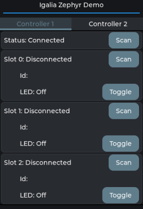
The sketch looks like this on the simulator:
Problem 17: Battery management
The peripheral devices are battery powered but so far we’re just trusting the the batteries have enough charge and that everything will just work. At the very least we should periodically monitor the battery charge, set some operational safety measures in the firmware and broadcast the battery level to the connected devices.
Solution
The XIAO nRF54L15 provides a mechanism to measure the battery level on demand using a load switch and an ADC.
To get a battery voltage measurement I need to enable the load switch, wait for it to turn on, sample the ADC connected to its output and convert the value to millivolts, doing the necessary adjustments to the reading (considering the voltage divider applied at the output).
Once I have this, there are two things I’ll want to do with it:
- Shutdown the firmware when the voltage is below a safe threshold. The SoC has a brownout reset generator and a glitch detector, but I’d rather detect and manage this via firmware.
- Publish the battery level, in percentage, using the standard BAS service.
This can be done with very little code:
/* Data of ADC io-channels specified in devicetree. */
static const struct adc_dt_spec adc_channels[] = {
    DT_FOREACH_PROP_ELEM(DT_PATH(zephyr_user), io_channels,
                         DT_SPEC_AND_COMMA)};

/* Battery load switch (for battery level measurement) */
static const struct device *const vbat_reg = DEVICE_DT_GET(DT_NODELABEL(vbat_pwr));

/* ADC data */
uint16_t buf;
struct adc_sequence sequence = {
    .buffer = &buf,
    .buffer_size = sizeof(buf),
};

void shutdown(void)
{
    gpio_remove_callback(button.port, &button_cb_data);
    gpio_remove_callback(button_board.port, &button_board_cb_data);
    led_state = 0;
    gpio_pin_set_dt(&led, led_state);
    gpio_pin_set_dt(&led_board, led_state);
    if (led_indication_enabled && !atomic_get(&indication_ongoing))
        k_work_schedule(&led_indicate_work, K_NO_WAIT);
    k_sleep(K_SECONDS(5));

    sys_poweroff();
    /* Should never reach here */
    while (1) {
        LOG_ERR("Shouldn't reach here");
        k_sleep(K_FOREVER);
    }
}

/* BAS handler */
void battery_voltage_check(struct k_work *work)
{
    int err;
    int32_t val_mv;
    uint8_t val_pct;

    regulator_enable(vbat_reg);
    k_sleep(K_MSEC(100));
    err = adc_read_dt(&adc_channels[ADC_CHANNEL_ID], &sequence);
    if (err < 0) {
        LOG_ERR("Could not read (%d)", err);
        return;
    }

    /*
     * If using differential mode, the 16 bit value
     * in the ADC sample buffer should be a signed 2's
     * complement value.
     */
    if (adc_channels[ADC_CHANNEL_ID].channel_cfg.differential)
        val_mv = (int32_t)((int16_t)buf);
    else
        val_mv = (int32_t)buf;
    err = adc_raw_to_millivolts_dt(&adc_channels[ADC_CHANNEL_ID], &val_mv);
    /* conversion to mV may not be supported, skip if not */
    if (err < 0) {
        LOG_ERR(" value in mV not available");
        return;
    }
    else {
        /* Correct the voltage taking into account the voltage divider */
        val_mv *= 2;
    }
    regulator_disable(vbat_reg);

    if (val_mv >= BATTERY_VOLTAGE_MAX) {
        val_pct = 100;
    } else if (val_mv <= BATTERY_VOLTAGE_MIN) {
        val_pct = 0;
        LOG_ERR("Critical battery voltage: %d mV - Shutting down!", val_mv);
        shutdown();
    } else {
        val_pct = ((val_mv - BATTERY_VOLTAGE_MIN) * 100) /
            (BATTERY_VOLTAGE_MAX - BATTERY_VOLTAGE_MIN);
    }

    bt_bas_set_battery_level(val_pct);
    LOG_DBG("Battery level: %d%%", val_pct);
}
Now I only have to schedule the battery_voltage_check()
function periodically. With this, the controller devices can subscribe
to the peripheral BAS service and get a notification every time the
battery level changes.
Problem 18: web GUI
In the previous blog post I set up a web server on the console board and ran a basic test. Now that I can control the devices through the display graphical interface, it’d be interesting to add a secondary web-based interface so that we can control them remotely as well.
The main requirements are:
- It must be lightweight and simple.
- It must be responsive and hassle-free.
- Both interfaces must be synchronized, i.e. any change in one of the interfaces must be updated in the other one in real time.
Solution
The first technical decision I need to take is how I’ll implement the web page in terms of the Zephyr web server api in a way that’s both lightweight and simple but also dynamic. A simple way to design a dynamic page would be to define a dynamic resource handler that will render different contents depending on the client requests. That means the firmware will be responsible of the content generation, which can be a resource-intensive task. Besides, the client won’t be aware of the interface changes unless it does a new request.
A much better option is to have a live connection between the server and the client through a websocket. As an additional improvement, I’ll offload the formatting and processing to the client as much as possible, so what the firmware will do is to serve a single template-based web page and the necessary javascript code for the client to do the formatting and page updating, and communicate the GUI changes from server to client and vice-versa using json messages through an established websocket.
This will minimize the amount of data to store in the firmware (only a small html page and some javascript code) and the GUI updates will be carried out using small json-formatted payloads.
The html contents (excluding the CSS definitions) can be as small as this:
<!DOCTYPE html>
<html lang="en">
  <head>
    <meta charset="UTF-8">
    <style>
    <!-- css definitions -->
    </style>
    <script src="main.js"></script>
    <title>Igalia Zephyr Demo</title>
  </head>
  <body>
    <main>
      <h1>Igalia Zephyr Demo</h1>

      <div id="controller_container">
      </div>

    </main>
  </body>

  <template id="controller_template">
    <div id="controller" class="controller_info">
      <div style="display:flex; align-items:center;">
        <h2>Controller device</h2>
        <input id="controller_scan" type="button" value="Scan" style="margin-left:20px;">
      </div>
      <ul>
        <li>
          Connection state: <span id="controller_state"></span>
          <span id="controller_scan_animation" class="waitdots"></span>
        </li>
      </ul>
      <!-- Slots divs go here -->
    </div>
  </template>

  <template id="slot_template">
    <div id="slot" class="slot_info">
      <div style="display:flex; align-items:center;">
        <h3>Slot</h3>
        <input id="slot_scan" type="button" value="Scan" style="margin-left:20px;">
      </div>
      <ul>
        <li>
          Connection state: <span id="slot_state"></span>
          <span id="slot_scan_animation" class="waitdots"></span>
        </li>
        <li id="slot_dev_id_li">
          Id: <span id="slot_dev_id"></span>
        </li>
        <li id="slot_battery_li">
          Battery: <span id="slot_battery"></span>
        </li>
        <li id="slot_led_li">
          LED state:
          <span id="slot_led_state" style="display:inline-block; width:50px"></span>
          <input id="slot_toggle_led" type="button" value="Toggle LED">
        </li>
      </ul>
    </div>
  </template>
</html>
And the javascript code that will run in the client will control the layout:
class Controller {
    constructor(idx, container_id) {
        let templ = document.getElementById('controller_template');
        let clone = templ.content.cloneNode(true);
        this.div = clone.querySelector('#controller');
        this.id = `controller_${idx}`;
        this.div.id = this.id;
        this.div.querySelector("h2").innerHTML = `Controller ${idx + 1}`;

        this.scan = this.div.querySelector('#controller_scan');
        this.scan.id = `${this.id}_scan`;

        this.state = this.div.querySelector('#controller_state');
        this.state.id = `${this.id}_state`;

        this.dots = this.div.querySelector('#controller_scan_animation');
        this.dots.id = `${this.id}_scan_animation`;

        // Insert controller div in the container
        let container = document.getElementById(container_id);
        container.appendChild(this.div);

        // Create and insert slot divs in the controller div
        this.slots = [
            new Slot(idx, 0),
            new Slot(idx, 1),
            new Slot(idx, 2)
        ];
        for (let s of this.slots) {
            this.div.appendChild(s.div);
        }

        // Initial element states
        this.state.innerHTML = 'Disconnected';
        this.dots.style.display = 'none';

        this.scan.addEventListener('click', (event) => {
            console.log(`Request scan on ${this.id}`);
            postAction(`{"target": -1, "action": ${Action.SCAN}, "param": ${idx}}`);
        })
    [...]
}

window.addEventListener('DOMContentLoaded', (ev) => {
    const ws = new WebSocket('/');

    controllers = [
        new Controller(0, "controller_container"),
        new Controller(1, "controller_container")];

    ws.onmessage = (event) => {
    const json = JSON.parse(event.data);
        for (let controller_idx in json) {
            if (controller_idx >= controllers.length)
                continue;
            controllers[controller_idx].update(json[controller_idx]);
        }
    }
})
Now, I need to define a suitable json schema to format the data passed between the server and the client. I’ll be using a fixed-size buffer in the firmware for the payload, so I need to make sure that the format produces compact enough messages. For simplicity, I also want every message to carry the whole peripheral state for all the devices, rather than partial updates.
This is the schema I came up with:
{
  "$schema": "https://json-schema.org/draft/2020-12/schema",
  "type": "object",
  "patternProperties": {
    "^[0-9]+$": {
      "type": "object",
      "description": "Controller status",
      "required": ["state", "slots"],
      "properties": {
        "state": {
          "type": "integer",
          "description": "Current state of the controller"
        },
        "slots": {
          "type": "array",
          "items": {
            "oneOf": [
              {
                "type": "null"
              },
              {
                "type": "object",
                "required": ["state", "id", "led", "bat"],
                "properties": {
                  "state": {
                    "type": "integer",
                    "description": "Current state of the slot"
                  },
                  "id": {
                    "type": "string",
                    "description": "String identifier of the connected peripheral"
                  },
                  "led": {
                    "type": "integer",
                    "description": "Peripheral LED state"
                  },
                  "bat": {
                    "type": "integer",
                    "minimum": 0,
                    "maximum": 100,
                    "description": "Peripheral battery level percentage"
                  }
                },
                "additionalProperties": false
              }
            ]
          },
          "minItems": 3,
          "maxItems": 3,
          "description": "Array containing the status of the controller slots"
        }
      },
      "additionalProperties": false
    }
  },
  "additionalProperties": false
}
With which I can format a message like this one:
{
    "0": {
        "state": 3,
        "slots": [
            null,
            {
                "state": 1,
                "id": "ZD-01",
                "led": 1,
                "bat": 97
            },
            null
        ]
    },
    "1": {
        "state": 0,
        "slots": [null,null,null]
    }
}
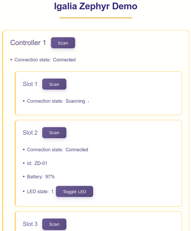
Once up and running, here’s how the web GUI looks like:
Problem 19: BLE security
At this point, the application is functionally complete in the sense that it showcases all the features I planned. However, so far we only cared about functionalities for a minimum viable product. There are many things we can improve and do properly rather than just for a simple demo, the most important of them is to enable BLE security and privacy.
Right now, all the BLE services I enabled are open. Anyone can connect to them using any client, which is a good first approach for testing and debugging. However, the demo will be installed in a conference or a fair with thousands of people, and it’d be totally vulnerable to any user that (maliciously or not) wants to interact with it without permission.
What I want to do is to allow the demo devices to establish connections between each other only, preventing other devices from joining. I don’t care much about data privacy, although that’d be an added bonus.
Solution
For these requirements, what I need to do is to enforce BLE security in all connections, which will give us protection to MITM attacks if I set up a way to require human interaction during the pairing process.
The basic security strategy I’ll implement is:
- All BLE services provided require authentication.
- Connection between any pair of devices requires L4 security (pairing).
- Pairing requires human interaction on the target device.
- The pairing process is allowed only during a limited time window. Additional pairing requests can be started manually.
- The amount of paired devices in each device is limited.
- Connection requires device proximity.
Since the only interactive user interface I have in the peripherals is a button (4 buttons in the controller devices), which I’m already using to toggle the LEDs, I need to multiplex it somehow to allow using it as a “keypress” for pairing confirmation, and also to start a pairing advertising process and, optionally, to “forget” all previous pairings, in case we ever need to do that. I chose to encode the different actions based on the duration of the button press. That way, a short press is normally used for toggling the LED, but it’s also used as a pairing confirmation during the pairing process. A long press is used to restart the advertising process, and a very long press to forget all previous pairings.
The LED also needs to encode the current status of the device. Since the advertising and pairing processes are only temporary, I’m setting the LED to blink during both of them: slowly during advertising and fast during the pairing window, where the user needs to press the button to confirm the pairing.
Implementing these security features means the connection handling is considerably more complex than before. Fortunately, the state-machine-based architecture I had in place is easy to extend and modify to incorporate the changes.
This should be enough to keep the application secure. Maybe even too paranoid, but I’d rather have no surprises during the deployment. For convenience, I’ll pre-pair all the devices so that they’ll be ready to work right after booting. A possible improvement for this setup would be to use directed advertising to reconnect to previously bond devices, but I’ll leave that for future iterations.
With this we’re done with the firmware / software part of the project, thanks for reading this far! The next thing to do is to turn this into a presentable demo and figure out the materials, assembly method and the setup logistics. I’ll go through the details in the next post of this series.