Why don't we do a demo? Part 2: software development
In part 1 of this series I talked about the beginning of this story and laid out the plan. In this post we’ll start the actual work, beginning with the software part.
Problem 5: base peripheral device
I’ll start with the most basic device: the peripheral. It will provide a simple BLE service to allow toggling the board LED remotely and displaying its current status.
Solution
The Zephyr samples are a good starting point for the firmware skeleton. The XIAO nRF54L15 is also well supported in Zephyr, so defining a custom BLE service and operating the on-board LED is not a challenge. A minimal sketch firmware with the basic functionality can be done reasonably quickly starting from scratch. To test the BLE service we can use a smartphone and nRF Connect for Mobile.
I probably don’t need to go all the trouble of doing a custom BLE service and characteristic for this, but it’s an exercise I’ll need to do at some point, and it has the added bonus of giving us full freedom to define the functionalities we want.
For the BLE services and characteristics, I picked up a random 128-bit UUID generated with https://www.uuidgenerator.net/version4.
The BLE-related boilerplate code for the basic functionality uses the appropriate macros to define the GATT service and characteristics:
/* LED service UUID: 46239800-1bed5-4c51-a215-9251faaae809 */
#define LED_SERVICE_UUID_VAL \
    BT_UUID_128_ENCODE(0x46239800, 0x1bed5, 0x4c51, 0xa215, 0x9251faaae809)

static struct bt_uuid_128 led_svc_uuid =
    BT_UUID_INIT_128(LED_SERVICE_UUID_VAL);

/* Characteristic UUID: 46239801-1bed5-4c51-a215-9251faaae809 */
static struct bt_uuid_128 led_char_uuid = BT_UUID_INIT_128(
    BT_UUID_128_ENCODE(0x46239801, 0x1bed5, 0x4c51, 0xa215, 0x9251faaae809));

/* Characteristic UUID: 46239802-1bed5-4c51-a215-9251faaae809 */
static struct bt_uuid_128 led_indication_char_uuid = BT_UUID_INIT_128(
    BT_UUID_128_ENCODE(0x46239802, 0x1bed5, 0x4c51, 0xa215, 0x9251faaae809));

[...]

BT_GATT_SERVICE_DEFINE(led_svc,
    BT_GATT_PRIMARY_SERVICE(&led_svc_uuid),
    BT_GATT_CHARACTERISTIC(&led_char_uuid.uuid,
            BT_GATT_CHRC_READ | BT_GATT_CHRC_WRITE,
            BT_GATT_PERM_READ | BT_GATT_PERM_WRITE,
            read_led_state, write_led_state, &led_state),
    BT_GATT_CHARACTERISTIC(&led_indication_char_uuid.uuid,
            BT_GATT_CHRC_INDICATE,
            BT_GATT_PERM_READ | BT_GATT_PERM_WRITE,
            NULL, NULL, NULL),
    BT_GATT_CCC(led_ccc_changed,
        BT_GATT_PERM_READ | BT_GATT_PERM_WRITE),
);
Where the read_led_state, write_led_state
and led_ccc_changed callbacks look something like this:
/*
 * LED state characteristic read callback.
 */
static ssize_t read_led_state(struct bt_conn *conn,
                             const struct bt_gatt_attr *attr, void *buf,
                             uint16_t len, uint16_t offset) {
    const uint8_t *val = attr->user_data;
    return bt_gatt_attr_read(conn, attr, buf, len, offset, val,
                sizeof(*val));
}

/*
 * LED state characteristic write callback.
 * A write to this characteristic will trigger a LED toggle, the data
 * sent is irrelevant so we can just ignore it.
 */
static ssize_t write_led_state(struct bt_conn *conn,
                              const struct bt_gatt_attr *attr, const void *buf,
                              uint16_t len, uint16_t offset, uint8_t flags) {
    ARG_UNUSED(conn);
    ARG_UNUSED(attr);
    ARG_UNUSED(buf);
    ARG_UNUSED(offset);
    ARG_UNUSED(flags);

    /*
     * Ignore received data (dummy): *((uint8_t *)buf)
     * and override (toggle) the led_state here as a side-effect.
     */
    LOG_DBG("LED toggle received: %d -> %d", led_state, led_state ? 0 : 1);
    led_state = led_state ? 0 : 1;
    gpio_pin_set_dt(&led, led_state);
    gpio_pin_set_dt(&led_board, led_state);
    if (led_indication_enabled)
        k_work_schedule(&led_indicate_work, K_NO_WAIT);

    return len;
}

/*
 * LED indication Client Characteristic Configuration callback.
 */
static void led_ccc_changed(const struct bt_gatt_attr *attr, uint16_t value)
{
    ARG_UNUSED(attr);

    led_indication_enabled = (value == BT_GATT_CCC_INDICATE);
    LOG_DBG("Indication %s", led_indication_enabled ? "enabled" : "disabled");
}
This should be good enough for now, we’ll surely need to complicate it later.
Problem 6: unexpected LED behavior
The user LED in the XIAO nRF54L15 turns off with gpio_pin_set_dt(&led, 1)
and on with gpio_pin_set_dt(&led, 0). Not a problem if
we only want to toggle it instead of setting a specific value, but not
ideal, since we also want to keep track of its current state and report
it.
Solution
This one’s easy. According to the schematic, this LED is active low, but the device tree for this SoC defines it as active high. Fixed and.
Problem 7: modeling the behavior of the central device
In the BLE central-peripheral architecture proposed, the peripheral will work as an autonomous device that provides a service but does no other action except when requested by the user through a button press. Other than that, it’ll sit there waiting for requests from the central (the controller device in our case), which will be the one governing the bulk of the application and, more importantly, managing the connection and doing the necessary actions to establish and monitor it.
Some of the tasks under the responsibility of the controller are:
- Scanning for peripherals.
- Connecting to peripherals.
- Service discovery.
- Keep track of the connected devices.
- Handle disconnection requests and lost connections.
We need a way to model this behavior into the controller so we can integrate these tasks with the rest of the firmware gracefully.
Solution
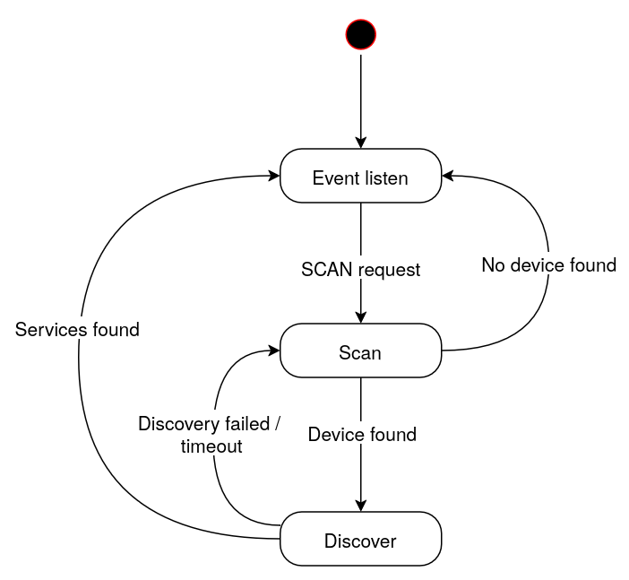
I’ll abstract the list of tasks above in a simple state machine that will run in a separate thread taking care of handling the connections, running the necessary actions as response to specific events, interacting with the rest of the firmware and reacting to the actions triggered by the user via the board buttons or by external sources.
That way, the main thread will set up the hardware and the necessary software subsystems, and the state machine will keep track of most of the BLE-related tasks and of the connected devices.
So, when the initialization is done, the main thread will start the state machine thread and then wait for events such as button presses, managing and restarting common services, while the state machine works on its own.
For our purposes we’ll only need three states:
- Event listen: the device waits for events from the user or from external sources. In the most basic scenario, it waits for a “scan” request, which will make the machine move to the “Scan” state.
- Scan: this state handles device scanning and connection. Once connected to a suitable device, the state machine will move to the “Discover” state. If no connection is done after a period of time, the machine will go back to the “Event listen” state.
- Discover: here, the firmware will run the discovery process for a connected peripheral, looking for a specific set of services and characteristics. If the process is successful, the controller will save the necessary data about the peripheral for later use and move to the “Event listen” state.
I can reuse most of this architecture as the basis for the console device as well, since it’ll be a central device to the controllers (remember the controllers are both central and peripheral BLE devices at the same time), so I can start sketching the console firmware as well as a generic central device.
Problem 8: designing the UX for the controller device
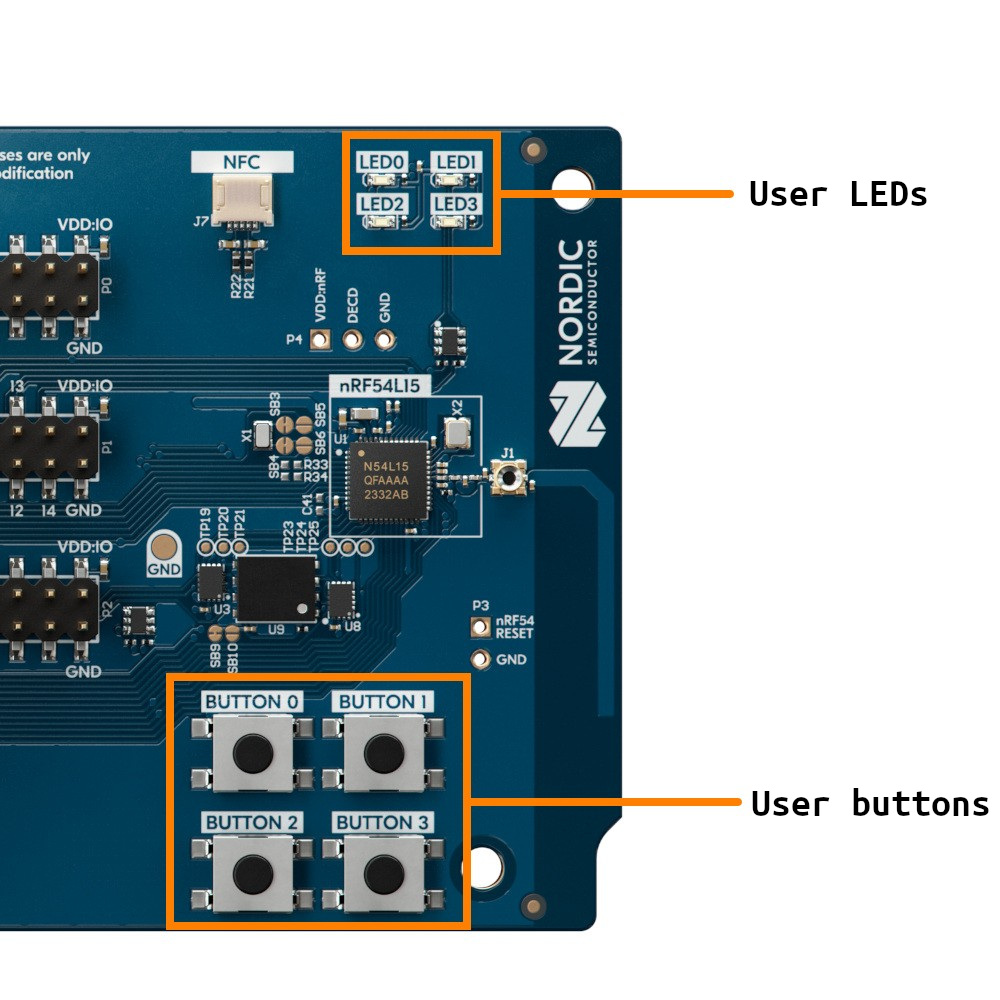
We need a way for the controller to interact with the connected peripherals, and in the controller boards (nRF54L15 DK) we have as user-facing devices four LEDs and four buttons. The operations we’ll need to perform are:
- Scan for peripherals.
- Disconnect from a connected peripheral.
- Toggle the LED of a connected peripheral.
- Check the status of the peripherals.
Solution
The most useful thing we could do with the board LEDs is to replicate the status of the peripheral LEDs. That way we could have a real-time overview of the state of the connected peripherals at all times.
The downside of this is that the board only has four LEDs, so if I want to show the status of the connected peripherals at a glance, I’m limited to four of them. And it’d be good to keep one LED to show the status of the controller itself, so lets start by limiting the amount of simultaneously connected peripherals to three.
Now, about the buttons, I’m going to need a way to perform at least three actions: scanning, disconnecting and toggling, and I’ll probably need to make room for additional actions down the road.
One option is to assign one button to each peripheral “slot”, so I could use button 0 to perform an action on slot 0, button 1 for slot 1, etc. In this case, I’d need to encode multiple actions on the same button: scanning and toggling at least.
A different approach is to use one or two buttons to select the active slot, and then the action buttons would operate on the selected slot. I feel like this method could be easier to adapt in case I need to add additional functionalities later, so this is what I’ll do:
- Button 0: select the next slot as the “active slot”.
- Button 1: “action button”, trigger an action on the peripheral connected in the active slot. For now, the action will be to toggle the LED.
- Button 2: select the previous slot as the “active slot”.
- Button 3: disconnect the peripheral in the active slot, if any, and start scanning on it.
I’ll also need a way to tell which one is the selected slot. Since I’m using the LEDs to represent the slots, an easy way to do this is by briefly blink the LED of the currently active slot when we use buttons 0 or 2 to cycle through the slots. Additionally, I can use the same method to encode whether the slot contains a connected peripheral or not, since I’m using a static LED to show the status of the peripheral LED (i.e. we can’t tell from a LED that’s off if the connected peripheral has its LED off or of there’s no peripheral connected at all): when cycling through the slots selecting the active one, the LED can do a short blink cycle to represent a disconnected slot and a long blink cycle to represent a connected one.
Problem 9: simulation and testing
During development, it’s very inconvenient to run all the firmware changes we do on real hardware, even if these boards can be flashed very fast. And for debugging and testing, relying on the hardware is overkill most of the time, even if we have direct access to a serial console and we have plenty of tracing possibilities. I’d need a better way to test our changes.
Solution
Fortunately, Zephyr includes a native simulator that allows to build a firmware as a native binary that I can run on the development machine using emulated devices. For my purposes, the native bsim boards even let me simulate the specific SoC used in the boards, including most of the SoC hardware, and run the firmware natively in BabbleSim to simulate real BLE usage.
This offers many advantages over testing on hardware:
- Faster development cycles.
- Easier debugging of runtime errors.
- Triggering of specific corner cases programmatically.
Ideally, what I’d like is to configure the environment so that I can selectively build and test the firmware on the simulator, or build a release firmware for the real hardware. A way to do this is to keep two separate project config files, create the necessary device tree overlay files for the different target boards (real and simulated) and compile certain parts of the firmware conditionally, so that I can enable test code and emulated devices only on the simulator build and I can keep hardware-dependent code only for the release build:
├── boards
│   ├── nrf52_bsim.conf
│   ├── nrf52_bsim.overlay
│   ├── nrf54l15bsim_nrf54l15_cpuapp.conf
│   └── nrf54l15bsim_nrf54l15_cpuapp.overlay
├── build.sh
├── CMakeLists.txt
├── flash.sh
├── Kconfig
├── prj.conf
├── prj_sim.conf
├── sim_bin
├── sim_build.sh
├── sim_run.sh
└── src
    ├── common.h
    ├── emul.c
    ├── emul.h
    ├── main.c
    ├── peripheral_mgmt.c
    ├── peripheral_mgmt.h
    ├── sim_test.c
    ├── sm.c
    └── sm.h
Code compiled conditionally for the simulator looks like this:
[...]
int main(void)
{
    static struct gpio_callback button_cb_data;
    int log_sources = log_src_cnt_get(0);
    int ret;
    int i;

#ifdef CONFIG_BOARD_NRF52_BSIM
    /* Set all logging to INFO level by default */
    for (i = 0; i < log_sources; i++) {
        log_filter_set(NULL, 0, i, LOG_LEVEL_INF);
    }
    int id = log_source_id_get("controller__main");
    log_filter_set(NULL, 0, id, LOG_LEVEL_DBG);
#else
    /* Disable all logging by default */
    for (i = 0; i < log_sources; i++) {
        log_filter_set(NULL, 0, i, LOG_LEVEL_NONE);
    }
#endif
From now on, I can do most of the development on the simulator, and once things are the way I want I can test them on the real hardware.
Problem 10: battery-powered peripheral setup
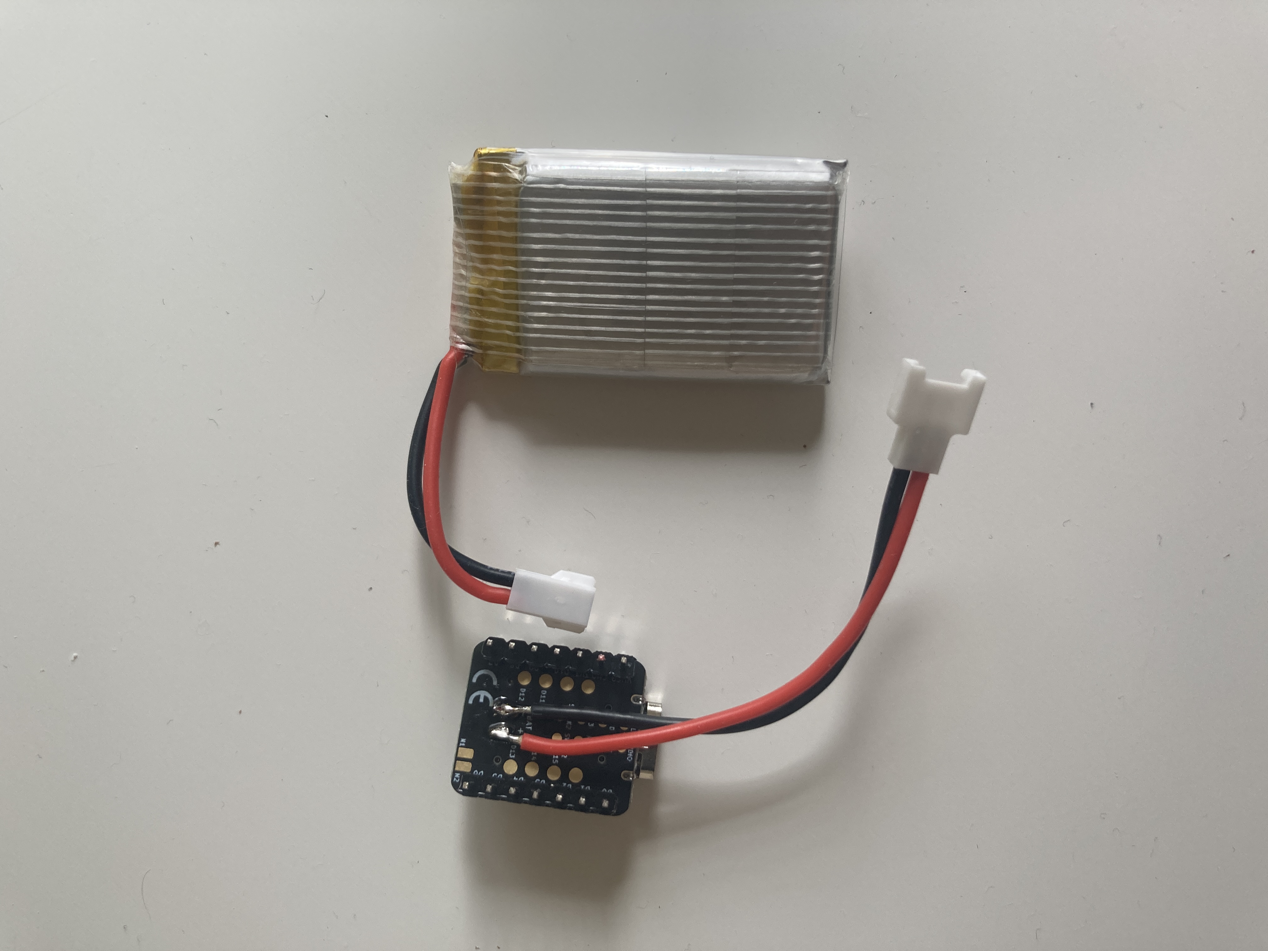
While the peripheral devices can be powered via USB, just the same as the bigger boards, the demo would be both more realistic and more diverse if we used batteries for them. The XIAO nRF54L15 is prepared for that and has battery pads and the necessary hardware to manage a LiPo battery. I need to provide the batteries and add the appropriate battery leads to the boards, though.
Solution
Any suitable LiPo battery will do, but I’ll search for batteries with an appropriate dimensions and capacity for this application.
I found this bundle containing five batteries and a charger, which should be good enough for our purposes: we can have up to 5 battery-powered peripherals and a convenient way to recharge the batteries if they’re easy to detach from the devices.
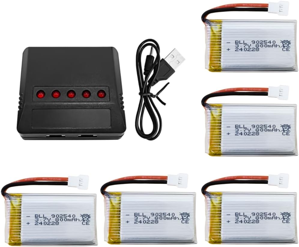
The battery connectors are Molex 51005, so I’ll also need to source a bunch of male and female leads. The pads are big enough to solder the leads to them with a conventional pen solder:
Problem 11: hardware unreliability
The XIAO nRF54L15 seems very flaky. In particular, after flashing it sometimes the device crashes and Zephyr reports a bus data error in the serial console. It seems to be random, it happens only after flashing some builds and it also seems to depend on timing.
Even worse, when battery-powered, the board won’t boot. When powered via USB, though, it will boot, and then I can plug in the battery, unplug the USB cable and the board will keep on running.
Solution
After some investigation and tests, it looks like the crashes are related to the logging through the UART console. Why, I don’t know. The kind of crashes I’m seeing right during booting are bus faults, and the first things I’d check for are null pointer dereferences and stack overflows, but in this case I’m not even getting a valid PC in the error report. Besides, there are a few signs that this will be hard to pinpoint:
- Altering the logging does cause different results.
- Different builds and flashings of the same firmware sometimes crash and sometimes don’t.
- It doesn’t seem related to the size of the logging stack.
- Deferred vs immediate logging causes different results.
- It doesn’t fail on the simulator.
- It seems related to timing.
- There’s a big randomness factor.
- The same firmware on the same SoC but on a different board design (nRF54L15 DK) works fine.
All of these hint that there’s some flakiness involved in the XIAO nRF54L15, particularly related to either power management, flashing or the use of the builtin USB for UART output.
Judging by some issues raised in the Seeed Studio forums, it looks like the USB-based SWD circuitry could be the cause of these problems. Regarding the problems booting when battery-powered, after asking about it in the forums, I got a response explaining the reason: when logging is enabled, the TX line back-feeds and powers up the USB-UART chip, causing a brownout and a shutdown/reboot.
The most reasonable fix or workaround for all of this is to simply disable all logging and UART usage when the board is battery-powered1. In order to do this, I created another build type that will be used for “production” releases. For the non-production builds (the ones I’ll use for development and debugging) I’ll keep logging disabled with the possibility of enabling it through shell commands. That’ll reduce the chances of crashing the system at boot time.
Problem 12: network connectivity in the console device
We can take advantage of the builtin web server capabilities provided by Zephyr for the console board. Since it’ll be governing the application and monitoring / controlling the connected devices, we’ll need a user interface to manage it. Implementing it in the form of a web interface should be easy enough, and it’d give us a lot of freedom to design the interface. The idea would be to connect the console board to a client (a laptop, for instance) using a point-to-point Ethernet link and have the client access the web page served by the console board.
The problem is that the board doesn’t have an Ethernet interface.
Solution
Everything’s not lost, though. The board doesn’t have an Ethernet interface but it has a general USB interface besides the one used for flashing and debugging. And, fortunately, the USB stack in Zephyr supports USB CDC NCM (Ethernet-over-USB) and we even have an example of the web server running on the same board we’re using for the console device, so setting it up shouldn’t be too much of an issue.
I can run the sample code on the board and check that it works, I can connect to it and see the web page published by the web server. Integrating the basic code into our sketchy console firmware is mostly painless, although I’m publishing only a placeholder web page. For now, that’s good enough. I’ll see what we can do with it later.
In the next post we’ll continue through the rest of the software development part of the project.
1: This is now documented in the Seeed Studio wiki.↩︎