First steps with Zephyr (II)
In the previous post we set up a Zephyr development environment and checked that we could build applications for multiple different targets. In this one we'll work on a sample application that we can use to showcase a few Zephyr features and as a template for other applications with a similar workflow.
We'll simulate a real work scenario and develop a firmware
for a hardware board (in this example it'll be
a Raspberry
Pi Pico 2W) and we'll set up a development workflow that
supports the native_sim target, so we can do most
of the programming and software prototyping on a simulated
environment without having to rely on the
hardware.
When developing for new hardware, it's a common practice
that the software teams need to start working on firmware
and drivers before the hardware is available, so the initial
stages of software development for new silicon and boards is
often tested on software or hardware emulators.
Then, after the prototyping is done we can deploy and test the
firmare on the real board. We'll see how we can do a simple
behavioral model of some of the devices we'll use in the final
hardware setup and how we can leverage this workflow to
unit-test and refine the firmware.
This post is a walkthrough of the whole application. You can find the code here.
Application description
The application we'll build and run on the Raspberry Pi Pico 2W will basically just listen for a button press. When the button is pressed the app will enqueue some work to be done by a processing thread and the result will be published via I2C for a controller to request. At the same time, it will configure two serial consoles, one for message logging and another one for a command shell that can be used for testing and debugging.
These are the main features we'll cover with this experiment:
- Support for multiple targets.
- Target-specific build and hardware configuration.
- Logging.
- Multiple console output.
- Zephyr shell with custom commands.
- Device emulation.
- GPIO handling.
- I2C target handling.
- Thread synchronization and message-passing.
- Deferred work (bottom halves).
Hardware setup
Besides the target board and the development machine, we'll be using a Linux-based development board that we can use to communicate with the Zephyr board via I2C. Anything will do here, I used a very old Raspberry Pi Model B that I had lying around.
The only additional peripheral we'll need is a physical button connected to a couple of board pins. If we don't have any, a jumper cable and a steady pulse will also work. Optionally, to take full advantage of the two serial ports, a USB - TTL UART converter will be useful. Here's how the full setup looks like:
   +--------------------------+
   |                          |    Eth
   |      Raspberry Pi        |---------------+
   |                          |               |
   +--------------------------+               |
      6    5   3                              |
      |    |   |                              |
      |   I2C I2C       /                     |
     GND  SCL SDA    __/ __                   |
      |    |   |    |     GND                 |
      |    |   |    |      |                  |
      18   7   6    4     38                  |
   +--------------------------+            +-------------+
   |                          |    USB     | Development |
   |   Raspberry Pi Pico 2W   |------------|   machine   |
   |                          |            +-------------+
   +--------------------------+                |
          13      12      11                   |
           |      |       |                    |
          GND   UART1    UART1                 |
           |     RX       TX                   |
           |      |       |                    |
          +-----------------+     USB          |
          |  USB - UART TTL |------------------+
          |    converter    |
          +-----------------+
For additional info on how to set up the Linux-based Raspberry Pi, see the appendix at the end.
Setting up the application files
Before we start coding we need to know how we'll structure the application. There are certain conventions and file structure that the build system expects to find under certain scenarios. This is how we'll structure the application (test_rpi):
test_rpi
├── boards
│   ├── native_sim_64.conf
│   ├── native_sim_64.overlay
│   ├── rpi_pico2_rp2350a_m33.conf
│   └── rpi_pico2_rp2350a_m33.overlay
├── CMakeLists.txt
├── Kconfig
├── prj.conf
├── README.rst
└── src
    ├── common.h
    ├── emul.c
    ├── main.c
    └── processing.c
Some of the files there we already know from
the previous
post: CMakeLists.txt
and prj.conf. All the application code will be in
the src directory, and we can structure it as we
want as long as we tell the build system about the files we
want to compile. For this application, the main code will be
in main.c, processing.c will contain
the code of the processing thread, and emul.c
will keep everything related to the device emulation for
the native_sim target and will be compiled only
when we build for that target. We describe this to the build
system through the contents of CMakeLists.txt:
cmake_minimum_required(VERSION 3.20.0)

find_package(Zephyr REQUIRED HINTS $ENV{ZEPHYR_BASE})
project(test_rpi)

target_sources(app PRIVATE src/main.c src/processing.c)
target_sources_ifdef(CONFIG_BOARD_NATIVE_SIM app PRIVATE src/emul.c)
In prj.conf we'll put the general Zephyr
configuration options for this application. Note that inside
the boards directory there are two additional
.conf files. These are target-specific options that will be
merged to the common ones in prj.conf depending
on the target we choose to build for.
Normally, most of the options we'll put in the .conf files will be already defined, but we can also define application-specific config options that we can later reference in the .conf files and the code. We can define them in the application-specific Kconfig file. The build system will it pick up as the main Kconfig file if it exists. For this application we'll define one additional config option that we'll use to configure the log level for the program, so this is how Kconfig will look like:
config TEST_RPI_LOG_LEVEL
	int "Default log level for test_rpi"
	default 4

source "Kconfig.zephyr"
Here we're simply prepending a config option before all the rest of the main Zephyr Kconfig file. We'll see how to use this option later.
Finally, the boards directory also contains
target-specific overlay files. These are regular device tree
overlays which are normally used to configure the
hardware. More about that in a while.
Main application architecture
The application flow is structured in two main threads: the
main
thread
and an additional processing thread that does its work
separately. The main thread runs the application entry point
(the main() function) and does all the software
and device set up. Normally it doesn't need to do anything
more, we can use it to start other threads and have them do
the rest of the work while the main thread sits idle, but in
this case we're doing some work with it instead of creating an
additional thread for that. Regarding the processing thread,
we can think of it as "application code" that runs on its
own and provides a simple interface to interact with the rest
of the system1.
Once the main thread has finished all the initialization process (creating threads, setting up callbacks, configuring devices, etc.) it sits in an infinite loop waiting for messages in a message queue. These messages are sent by the processing thread, which also runs in a loop waiting for messages in another queue. The messages to the processing thread are sent, as a result of a button press, by the GPIO ISR callback registered (actually, by the bottom half triggered by it and run by a workqueue thread). Ignoring the I2C part for now, this is how the application flow would look like:
    Main thread    Processing thread    Workqueue thread     GPIO ISR
        |                  |                    |                |
        |                  |                    |<--------------| |
        |                  |<------------------| |           (1) |
        |                 | |               (2) |                |
        |<----------------| |                   |                |
       | |             (3) |                    |                |
        |                  |                    |                |
Once the button press is detected, the GPIO ISR calls a callback we registered in the main setup code. The callback defers the work (1) through a workqueue (we'll see why later), which sends some data to the processing thread (2). The data it'll send is just an integer: the current uptime in seconds. The processing thread will then do some processing using that data (convert it to a string) and will send the processed data to the main thread (3). Let's take a look at the code that does all this.
Thread creation
As we mentioned, the main thread will be responsible for, among other tasks, spawning other threads. In our example it will create only one additional thread.
#include <zephyr/kernel.h>

#define THREAD_STACKSIZE	2048
#define THREAD_PRIORITY		10

K_THREAD_STACK_DEFINE(processing_stack, THREAD_STACKSIZE);
struct k_thread processing_thread;

int main(void)
{
	[...]

	/* Thread initialization */
	k_thread_create(&processing_thread, processing_stack,
			THREAD_STACKSIZE, data_process,
			&in_msgq, &out_msgq, NULL,
			THREAD_PRIORITY, 0, K_FOREVER);
	k_thread_name_set(&processing_thread, "processing");
	k_thread_start(&processing_thread);
We'll see what the data_process() function does
in a while. For now, notice we're passing two message queues,
one for input and one for output, as parameters for that
function. These will be used as the interface to connect the
processing thread to the rest of the firmware.
GPIO handling
Zephyr's device tree support greatly simplifies device handling and makes it really easy to parameterize and handle device operations in an abstract way. In this example, we define and reference the GPIO for the button in our setup using a platform-independent device tree node:
#define ZEPHYR_USER_NODE DT_PATH(zephyr_user)
const struct gpio_dt_spec button = GPIO_DT_SPEC_GET_OR(
	ZEPHYR_USER_NODE, button_gpios, {0});
This looks for a "button-gpios" property in
the "zephyr,user"
node in the device tree of the target platform and
initializes
a gpio_dt_spec
property containing the GPIO pin information defined in the
device tree. Note that this initialization and the check for
the "zephyr,user" node are static and happen at compile time
so, if the node isn't found, the error will be caught by the
build process.
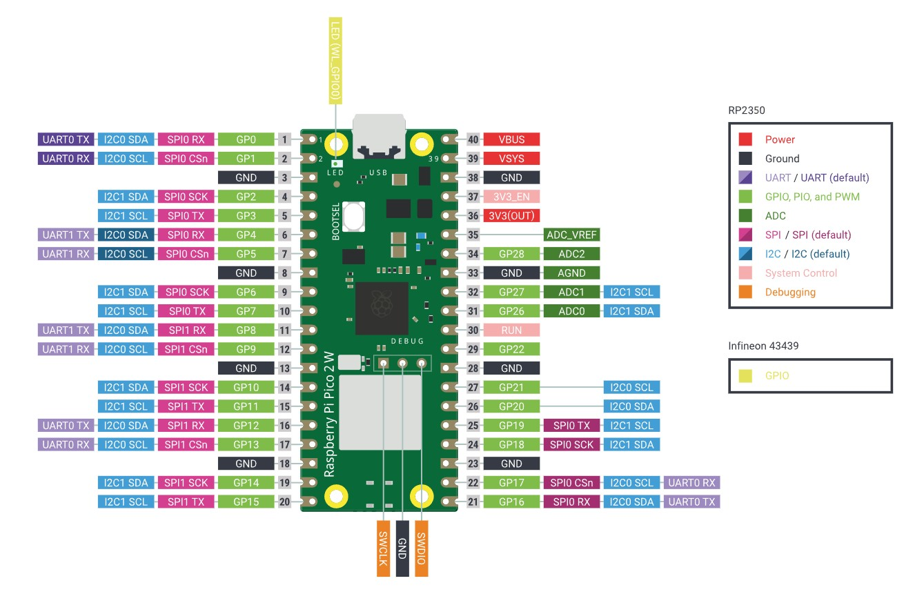
This is how the node is defined for the Raspberry Pi Pico 2W:
/ {

[...]

	zephyr,user {
		button-gpios = <&gpio0 2 (GPIO_ACTIVE_LOW | GPIO_PULL_UP)>;
	};
};
This defines the GPIO to be used as the second GPIO from bank 0, it'll be set up with an internal pull-up resistor and will be active-low. See the device tree GPIO API for details on the specification format. In the board, that GPIO is routed to pin 4:
Now we'll use the GPIO API to configure the GPIO as defined and to add a callback that will run when the button is pressed:
if (!gpio_is_ready_dt(&button)) {
	LOG_ERR("Error: button device %s is not ready",
	       button.port->name);
	return 0;
}
ret = gpio_pin_configure_dt(&button, GPIO_INPUT);
if (ret != 0) {
	LOG_ERR("Error %d: failed to configure %s pin %d",
	       ret, button.port->name, button.pin);
	return 0;
}
ret = gpio_pin_interrupt_configure_dt(&button,
                                      GPIO_INT_EDGE_TO_ACTIVE);
if (ret != 0) {
	LOG_ERR("Error %d: failed to configure interrupt on %s pin %d",
		ret, button.port->name, button.pin);
	return 0;
}
gpio_init_callback(&button_cb_data, button_pressed, BIT(button.pin));
gpio_add_callback(button.port, &button_cb_data);
We're configuring the pin as an input and then we're enabling interrupts for it when it goes to logical level "high". In this case, since we defined it as active-low, the interrupt will be triggered when the pin transitions from the stable pulled-up voltage to ground.
Finally, we're initializing and adding a callback function that will be called by the ISR when it detects that this GPIO goes active. We'll use this callback to start an action from a user event. The specific interrupt handling is done by the target-specific device driver2 and we don't have to worry about that, our code can remain device-independent.
NOTE: The callback we'll define is meant as a simple exercise for illustrative purposes. Zephyr provides an input subsystem to handle cases like this properly.
What we want to do in the callback is to send a message to
the processing thread. The communication input channel to the
thread is the in_msgq message queue, and the data
we'll send is a simple 32-bit integer with the number of
uptime seconds. But before doing that, we'll first de-bounce
the button press using a simple idea: to schedule the message
delivery to a
workqueue
thread:
/*
 * Deferred irq work triggered by the GPIO IRQ callback
 * (button_pressed). This should run some time after the ISR, at which
 * point the button press should be stable after the initial bouncing.
 *
 * Checks the button status and sends the current system uptime in
 * seconds through in_msgq if the the button is still pressed.
 */
static void debounce_expired(struct k_work *work)
{
	unsigned int data = k_uptime_seconds();
	ARG_UNUSED(work);

	if (gpio_pin_get_dt(&button))
		k_msgq_put(&in_msgq, &data, K_NO_WAIT);
}

static K_WORK_DELAYABLE_DEFINE(debounce_work, debounce_expired);

/*
 * Callback function for the button GPIO IRQ.
 * De-bounces the button press by scheduling the processing into a
 * workqueue.
 */
void button_pressed(const struct device *dev, struct gpio_callback *cb,
		    uint32_t pins)
{
	k_work_reschedule(&debounce_work, K_MSEC(30));
}
That way, every unwanted oscillation will cause a
re-scheduling of the message delivery (replacing any prior
scheduling). debounce_expired will eventually
read the GPIO status and send the message.
Thread synchronization and messaging
As I mentioned earlier, the interface with the processing
thread consists on two message queues, one for input and one for
output. These are defined statically with
the K_MSGQ_DEFINE macro:
#define PROC_MSG_SIZE		8

K_MSGQ_DEFINE(in_msgq, sizeof(int), 1, 1);
K_MSGQ_DEFINE(out_msgq, PROC_MSG_SIZE, 1, 1);
Both queues have space to hold only one message each. For the input queue (the one we'll use to send messages to the processing thread), each message will be one 32-bit integer. The messages of the output queue (the one the processing thread will use to send messages) are 8 bytes long.
Once the main thread is done initializing everything, it'll stay in an infinite loop waiting for messages from the processing thread. The processing thread will also run a loop waiting for incoming messages in the input queue, which are sent by the button callback, as we saw earlier, so the message queues will be used both for transferring data and for synchronization. Since the code running in the processing thread is so small, I'll paste it here in its entirety:
static char data_out[PROC_MSG_SIZE];

/*
 * Receives a message on the message queue passed in p1, does some
 * processing on the data received and sends a response on the message
 * queue passed in p2.
 */
void data_process(void *p1, void *p2, void *p3)
{
	struct k_msgq *inq = p1;
	struct k_msgq *outq = p2;
	ARG_UNUSED(p3);

	while (1) {
		unsigned int data;

		k_msgq_get(inq, &data, K_FOREVER);
		LOG_DBG("Received: %d", data);

		/* Data processing: convert integer to string */
		snprintf(data_out, sizeof(data_out), "%d", data);

		k_msgq_put(outq, data_out, K_NO_WAIT);
	}
}I2C target implementation
Now that we have a way to interact with the program by inputting an external event (a button press), we'll add a way for it to communicate with the outside world: we're going to turn our device into a I2C target that will listen for command requests from a controller and send data back to it. In our setup, the controller will be Linux-based Raspberry Pi, see the diagram in the Hardware setup section above for details on how the boards are connected.
In order to define an I2C target we first need a suitable device defined in the device tree. To abstract the actual target-dependent device, we'll define and use an alias for it that we can redefine for every supported target. For instance, for the Raspberry Pi Pico 2W we define this alias in its device tree overlay:
/ {
	[...]

	aliases {
                i2ctarget = &i2c0;
	};
Where i2c0 is originally defined like this:
i2c0: i2c@40090000 {
	compatible = "raspberrypi,pico-i2c", "snps,designware-i2c";
	#address-cells = <1>;
	#size-cells = <0>;
	reg = <0x40090000 DT_SIZE_K(4)>;
	resets = <&reset RPI_PICO_RESETS_RESET_I2C0>;
	clocks = <&clocks RPI_PICO_CLKID_CLK_SYS>;
	interrupts = <36 RPI_PICO_DEFAULT_IRQ_PRIORITY>;
	interrupt-names = "i2c0";
	status = "disabled";
};
and then enabled:
&i2c0 {
	clock-frequency = <I2C_BITRATE_STANDARD>;
	status = "okay";
	pinctrl-0 = <&i2c0_default>;
	pinctrl-names = "default";
};
So now in the code we can reference
the i2ctarget alias to load the device info and
initialize it:
/*
 * Get I2C device configuration from the devicetree i2ctarget alias.
 * Check node availability at buid time.
 */
#define I2C_NODE	DT_ALIAS(i2ctarget)
#if !DT_NODE_HAS_STATUS_OKAY(I2C_NODE)
#error "Unsupported board: i2ctarget devicetree alias is not defined"
#endif
const struct device *i2c_target = DEVICE_DT_GET(I2C_NODE);
To register the device as a target, we'll use
the i2c_target_register()
function, which takes the loaded device tree device and an
I2C target configuration (struct
i2c_target_config) containing the I2C
address we choose for it and a set of callbacks for all the
possible events. It's in these callbacks where we'll define the
target's functionality:
#define I2C_ADDR 0x60
[...]
static struct i2c_target_callbacks target_callbacks = {
.write_requested = write_requested_cb,
.write_received = write_received_cb,
.read_requested = read_requested_cb,
.read_processed = read_processed_cb,
.stop = stop_cb,
};
[...]
int main(void)
{
struct i2c_target_config target_cfg = {
.address = I2C_ADDR,
.callbacks = &target_callbacks,
};
if (i2c_target_register(i2c_target, &target_cfg) < 0) {
LOG_ERR("Failed to register target");
return -1;
}Each of those callbacks will be called as a response from an event started by the controller. Depending on how we want to define the target we'll need to code the callbacks to react appropriately to the controller requests. For this application we'll define a register that the controller can read to get a timestamp (the firmware uptime in seconds) from the last time the button was pressed. The number will be received as an 8-byte ASCII string.
If the controller is the Linux-based Raspberry Pi, we can use the i2c-tools to poll the target and read from it:
# Scan the I2C bus:
$ i2cdetect -y 0
     0  1  2  3  4  5  6  7  8  9  a  b  c  d  e  f
00:                         -- -- -- -- -- -- -- --
10: -- -- -- -- -- -- -- -- -- -- -- -- -- -- -- --
20: -- -- -- -- -- -- -- -- -- -- -- -- -- -- -- --
30: -- -- -- -- -- -- -- -- -- -- -- -- -- -- -- --
40: -- -- -- -- -- -- -- -- -- -- -- -- -- -- -- --
50: -- -- -- -- -- -- -- -- -- -- -- -- -- -- -- --
60: 60 -- -- -- -- -- -- -- -- -- -- -- -- -- -- --
70: -- -- -- -- -- -- -- --

# I2C bus 0: issue command 0 (read uptime) on device 0x60:
# - Send byte 0 to device with address 0x60
# - Read back 8 bytes
$ i2ctransfer -y 0 w1@0x60 0 r8
0x36 0x33 0x00 0x00 0x00 0x00 0x00 0x00
We basically want the device to react when the controller sends a write request (to select the register and prepare the data), when it sends a read request (to send the data bytes back to the controller) and when it sends a stop condition.
To handle the data to be sent, the I2C callback functions manage an internal buffer that will hold the string data to send to the controller, and we'll load this buffer with the contents of a source buffer that's updated every time the main thread receives data from the processing thread (a double-buffer scheme). Then, when we program an I2C transfer we walk this internal buffer sending each byte to the controller as we receive read requests. When the transfer finishes or is aborted, we reload the buffer and rewind it for the next transfer:
typedef enum {
	I2C_REG_UPTIME,
	I2C_REG_NOT_SUPPORTED,

	I2C_REG_DEFAULT = I2C_REG_UPTIME
} i2c_register_t;

/* I2C data structures */
static char i2cbuffer[PROC_MSG_SIZE];
static int i2cidx = -1;
static i2c_register_t i2creg = I2C_REG_DEFAULT;

[...]

/*
 * Callback called on a write request from the controller.
 */
int write_requested_cb(struct i2c_target_config *config)
{
	LOG_DBG("I2C WRITE start");
	return 0;
}

/*
 * Callback called when a byte was received on an ongoing write request
 * from the controller.
 */
int write_received_cb(struct i2c_target_config *config, uint8_t val)
{
	LOG_DBG("I2C WRITE: 0x%02x", val);
	i2creg = val;
	if (val == I2C_REG_UPTIME)
		i2cidx = -1;

	return 0;
}

/*
 * Callback called on a read request from the controller.
 * If it's a first read, load the output buffer contents from the
 * current contents of the source data buffer (str_data).
 *
 * The data byte sent to the controller is pointed to by val.
 * Returns:
 *   0 if there's additional data to send
 *   -ENOMEM if the byte sent is the end of the data transfer
 *   -EIO if the selected register isn't supported
 */
int read_requested_cb(struct i2c_target_config *config, uint8_t *val)
{
	if (i2creg != I2C_REG_UPTIME)
		return -EIO;

	LOG_DBG("I2C READ started. i2cidx: %d", i2cidx);
	if (i2cidx < 0) {
		/* Copy source buffer to the i2c output buffer */
		k_mutex_lock(&str_data_mutex, K_FOREVER);
		strncpy(i2cbuffer, str_data, PROC_MSG_SIZE);
		k_mutex_unlock(&str_data_mutex);
	}
	i2cidx++;
	if (i2cidx == PROC_MSG_SIZE) {
		i2cidx = -1;
		return -ENOMEM;
	}
	*val = i2cbuffer[i2cidx];
	LOG_DBG("I2C READ send: 0x%02x", *val);

	return 0;
}

/*
 * Callback called on a continued read request from the
 * controller. We're implementing repeated start semantics, so this will
 * always return -ENOMEM to signal that a new START request is needed.
 */
int read_processed_cb(struct i2c_target_config *config, uint8_t *val)
{
	LOG_DBG("I2C READ continued");
	return -ENOMEM;
}

/*
 * Callback called on a stop request from the controller. Rewinds the
 * index of the i2c data buffer to prepare for the next send.
 */
int stop_cb(struct i2c_target_config *config)
{
	i2cidx = -1;
	LOG_DBG("I2C STOP");
	return 0;
}
int main(void)
{
	[...]

	while (1) {
		char buffer[PROC_MSG_SIZE];

		k_msgq_get(&out_msgq, buffer, K_FOREVER);
		LOG_DBG("Received: %s", buffer);
		k_mutex_lock(&str_data_mutex, K_FOREVER);
		strncpy(str_data, buffer, PROC_MSG_SIZE);
		k_mutex_unlock(&str_data_mutex);
	}
Device emulation
The application logic is done at this point, and we were careful to write it in a platform-agnostic way. As mentioned earlier, all the target-specific details are abstracted away by the device tree and the Zephyr APIs. Although we're developing with a real deployment board in mind, it's very useful to be able to develop and test using a behavioral model of the hardware that we can program to behave as close to the real hardware as we need and that we can run on our development machine without the cost and restrictions of the real hardware.
To do this, we'll rely on the native_sim board3, which implements the core OS
services on top of a POSIX compatibility layer, and we'll add
code to simulate the button press and the I2C
requests.
Emulating a button press
We'll use
the gpio_emul
driver as a base for our emulated
button. The native_sim device tree already defines
an emulated GPIO bank for this:
gpio0: gpio_emul {
	status = "okay";
	compatible = "zephyr,gpio-emul";
	rising-edge;
	falling-edge;
	high-level;
	low-level;
	gpio-controller;
	#gpio-cells = <2>;
};
So we can define the GPIO to use for our button in the native_sim board overlay:
/ {
	[...]

	zephyr,user {
		button-gpios = <&gpio0 0 GPIO_ACTIVE_HIGH>;
	};
};
We'll model the button press as a four-phase event consisting
on an initial status change caused by the press, then a
semi-random rebound phase, then a phase of signal
stabilization after the rebounds stop, and finally a button
release. Using the gpio_emul API it'll look like
this:
/*
 * Emulates a button press with bouncing.
 */
static void button_press(void)
{
	const struct device *dev = device_get_binding(button.port->name);
	int n_bounces = sys_rand8_get() % 10;
	int state = 1;
	int i;

	/* Press */
	gpio_emul_input_set(dev, 0, state);
	/* Bouncing */
	for (i = 0; i < n_bounces; i++) {
		state = state ? 0: 1;
		k_busy_wait(1000 * (sys_rand8_get() % 10));
		gpio_emul_input_set(dev, 0, state);
	}
	/* Stabilization */
	gpio_emul_input_set(dev, 0, 1);
	k_busy_wait(100000);
	/* Release */
	gpio_emul_input_set(dev, 0, 0);
}
The driver will take care of checking if the state changes need to raise interrupts, depending on the GPIO configuration, and will trigger the registered callback that we defined earlier.
Emulating an I2C controller
As with the button emulator, we'll rely on an existing
emulated device driver for
this: i2c_emul. Again,
the device tree for the target already defines the node we
need:
i2c0: i2c@100 {
	status = "okay";
	compatible = "zephyr,i2c-emul-controller";
	clock-frequency = <I2C_BITRATE_STANDARD>;
	#address-cells = <1>;
	#size-cells = <0>;
	#forward-cells = <1>;
	reg = <0x100 4>;
};
So we can define a machine-independent alias that we can reference in the code:
/ {
	aliases {
		i2ctarget = &i2c0;
	};
The events we need to emulate are the requests sent by the
controller: READ start, WRITE start and STOP. We can define
these based on
the i2c_transfer()
API function which will, in this case, use
the i2c_emul
driver implementation to simulate the transfer. As in the
GPIO emulation case, this will trigger the appropriate
callbacks. The implementation of our controller requests looks
like this:
/*
 * A real controller may want to continue reading after the first
 * received byte. We're implementing repeated-start semantics so we'll
 * only be sending one byte per transfer, but we need to allocate space
 * for an extra byte to process the possible additional read request.
 */
static uint8_t emul_read_buf[2];

/*
 * Emulates a single I2C READ START request from a controller.
 */
static uint8_t *i2c_emul_read(void)
{
	struct i2c_msg msg;
	int ret;

	msg.buf = emul_read_buf;
	msg.len = sizeof(emul_read_buf);
	msg.flags = I2C_MSG_RESTART | I2C_MSG_READ;
	ret = i2c_transfer(i2c_target, &msg, 1, I2C_ADDR);
	if (ret == -EIO)
		return NULL;

	return emul_read_buf;
}

static void i2c_emul_write(uint8_t *data, int len)
{
	struct i2c_msg msg;

	/*
	 * NOTE: It's not explicitly said anywhere that msg.buf can be
	 * NULL even if msg.len is 0. The behavior may be
	 * driver-specific and prone to change so we're being safe here
	 * by using a 1-byte buffer.
	 */
	msg.buf = data;
	msg.len = len;
	msg.flags = I2C_MSG_WRITE;
	i2c_transfer(i2c_target, &msg, 1, I2C_ADDR);
}

/*
 * Emulates an explicit I2C STOP sent from a controller.
 */
static void i2c_emul_stop(void)
{
	struct i2c_msg msg;
	uint8_t buf = 0;

	/*
	 * NOTE: It's not explicitly said anywhere that msg.buf can be
	 * NULL even if msg.len is 0. The behavior may be
	 * driver-specific and prone to change so we're being safe here
	 * by using a 1-byte buffer.
	 */
	msg.buf = &buf;
	msg.len = 0;
	msg.flags = I2C_MSG_WRITE | I2C_MSG_STOP;
	i2c_transfer(i2c_target, &msg, 1, I2C_ADDR);
}
Now we can define a complete request for an "uptime read" operation in terms of these primitives:
/*
* Emulates an I2C "UPTIME" command request from a controller using
* repeated start.
*/
static void i2c_emul_uptime(const struct shell *sh, size_t argc, char **argv)
{
uint8_t buffer[PROC_MSG_SIZE] = {0};
i2c_register_t reg = I2C_REG_UPTIME;
int i;
i2c_emul_write((uint8_t *)®, 1);
for (i = 0; i < PROC_MSG_SIZE; i++) {
uint8_t *b = i2c_emul_read();
if (b == NULL)
break;
buffer[i] = *b;
}
i2c_emul_stop();
if (i == PROC_MSG_SIZE) {
shell_print(sh, "%s", buffer);
} else {
shell_print(sh, "Transfer error");
}
}Ok, so now that we have implemented all the emulated operations we needed, we need a way to trigger them on the emulated environment. The Zephyr shell is tremendously useful for cases like this.
Shell commands
The shell module in Zephyr has a lot of useful features that we can use for debugging. It's quite extensive and talking about it in detail is out of the scope of this post, but I'll show how simple it is to add a few custom commands to trigger the button presses and the I2C controller requests from a console. In fact, for our purposes, the whole thing is as simple as this:
SHELL_CMD_REGISTER(buttonpress, NULL, "Simulates a button press", button_press);
SHELL_CMD_REGISTER(i2cread, NULL, "Simulates an I2C read request", i2c_emul_read);
SHELL_CMD_REGISTER(i2cuptime, NULL, "Simulates an I2C uptime request", i2c_emul_uptime);
SHELL_CMD_REGISTER(i2cstop, NULL, "Simulates an I2C stop request", i2c_emul_stop);
We'll enable these commands only when building for
the native_sim board. With the configuration
provided, once we run the application we'll have the log
output in stdout and the shell UART connected to a pseudotty,
so we can access it in a separate terminal and run these
commands while we see the output in the terminal where we ran
the application:
$ ./build/zephyr/zephyr.exe
WARNING: Using a test - not safe - entropy source
uart connected to pseudotty: /dev/pts/16
*** Booting Zephyr OS build v4.1.0-6569-gf4a0beb2b7b1 ***

# In another terminal
$ screen /dev/pts/16

uart:~$
uart:~$ help
Please press the <Tab> button to see all available commands.
You can also use the <Tab> button to prompt or auto-complete all commands or its subcommands.
You can try to call commands with <-h> or <--help> parameter for more information.

Shell supports following meta-keys:
  Ctrl + (a key from: abcdefklnpuw)
  Alt  + (a key from: bf)
Please refer to shell documentation for more details.

Available commands:
  buttonpress  : Simulates a button press
  clear        : Clear screen.
  device       : Device commands
  devmem       : Read/write physical memory
                 Usage:
                 Read memory at address with optional width:
                 devmem <address> [<width>]
                 Write memory at address with mandatory width and value:
                 devmem <address> <width> <value>
  help         : Prints the help message.
  history      : Command history.
  i2cread      : Simulates an I2C read request
  i2cstop      : Simulates an I2C stop request
  i2cuptime    : Simulates an I2C uptime request
  kernel       : Kernel commands
  rem          : Ignore lines beginning with 'rem '
  resize       : Console gets terminal screen size or assumes default in case
                 the readout fails. It must be executed after each terminal
                 width change to ensure correct text display.
  retval       : Print return value of most recent command
  shell        : Useful, not Unix-like shell commands.
To simulate a button press (ie. capture the current uptime):
uart:~$ buttonpressAnd the log output should print the enabled debug messages:
[00:00:06.300,000] <dbg> test_rpi: data_process: Received: 6
[00:00:06.300,000] <dbg> test_rpi: main: Received: 6
If we now simulate an I2C uptime command request we should get the captured uptime as a string:
uart:~$ i2cuptime
6
We can check the log to see how the I2C callbacks ran:
[00:01:29.400,000] <dbg> test_rpi: write_requested_cb: I2C WRITE start
[00:01:29.400,000] <dbg> test_rpi: write_received_cb: I2C WRITE: 0x00
[00:01:29.400,000] <dbg> test_rpi: stop_cb: I2C STOP
[00:01:29.400,000] <dbg> test_rpi: read_requested_cb: I2C READ started. i2cidx: -1
[00:01:29.400,000] <dbg> test_rpi: read_requested_cb: I2C READ send: 0x36
[00:01:29.400,000] <dbg> test_rpi: read_processed_cb: I2C READ continued
[00:01:29.400,000] <dbg> test_rpi: read_requested_cb: I2C READ started. i2cidx: 0
[00:01:29.400,000] <dbg> test_rpi: read_requested_cb: I2C READ send: 0x00
[00:01:29.400,000] <dbg> test_rpi: read_processed_cb: I2C READ continued
[00:01:29.400,000] <dbg> test_rpi: read_requested_cb: I2C READ started. i2cidx: 1
[00:01:29.400,000] <dbg> test_rpi: read_requested_cb: I2C READ send: 0x00
[00:01:29.400,000] <dbg> test_rpi: read_processed_cb: I2C READ continued
[00:01:29.400,000] <dbg> test_rpi: read_requested_cb: I2C READ started. i2cidx: 2
[00:01:29.400,000] <dbg> test_rpi: read_requested_cb: I2C READ send: 0x00
[00:01:29.400,000] <dbg> test_rpi: read_processed_cb: I2C READ continued
[00:01:29.400,000] <dbg> test_rpi: read_requested_cb: I2C READ started. i2cidx: 3
[00:01:29.400,000] <dbg> test_rpi: read_requested_cb: I2C READ send: 0x00
[00:01:29.400,000] <dbg> test_rpi: read_processed_cb: I2C READ continued
[00:01:29.400,000] <dbg> test_rpi: read_requested_cb: I2C READ started. i2cidx: 4
[00:01:29.400,000] <dbg> test_rpi: read_requested_cb: I2C READ send: 0x00
[00:01:29.400,000] <dbg> test_rpi: read_processed_cb: I2C READ continued
[00:01:29.400,000] <dbg> test_rpi: read_requested_cb: I2C READ started. i2cidx: 5
[00:01:29.400,000] <dbg> test_rpi: read_requested_cb: I2C READ send: 0x00
[00:01:29.400,000] <dbg> test_rpi: read_processed_cb: I2C READ continued
[00:01:29.400,000] <dbg> test_rpi: read_requested_cb: I2C READ started. i2cidx: 6
[00:01:29.400,000] <dbg> test_rpi: read_requested_cb: I2C READ send: 0x00
[00:01:29.400,000] <dbg> test_rpi: read_processed_cb: I2C READ continued
[00:01:29.400,000] <dbg> test_rpi: stop_cb: I2C STOP
Appendix: Linux set up on the Raspberry Pi
This is the process I followed to set up a Linux system on a Raspberry Pi (very old, model 1 B). There are plenty of instructions for this on the Web, and you can probably just pick up a pre-packaged and pre-configured Raspberry Pi OS and get done with it faster, so I'm adding this here for completeness and because I want to have a finer grained control of what I put into it.
The only harware requirement is an SD card with two partitions: a small (~50MB) FAT32 boot partition and the rest of the space for the rootfs partition, which I formatted as ext4. The boot partition should contain a specific set of configuration files and binary blobs, as well as the kernel that we'll build and the appropriate device tree binary. See the official docs for more information on the boot partition contents and this repo for the binary blobs. For this board, the minimum files needed are:
- bootcode.bin: the second-stage bootloader, loaded by the first-stage bootloader in the BCM2835 ROM. Run by the GPU.
- start.elf: GPU firmware, starts the ARM CPU.
- fixup.dat: needed by start.elf. Used to configure the SDRAM.
- kernel.img: this is the kernel image we'll build.
- dtb files and overlays.
And, optionally but very recommended:
- config.txt: bootloader configuration.
- cmdline.txt: kernel command-line parameters.
In practice, pretty much all Linux setups will also have
these files. For our case we'll need to add one additional
config entry to the config.txt file in order to
enable the I2C bus:
dtparam=i2c_arm=onOnce we have the boot partition populated with the basic required files (minus the kernel and dtb files), the two main ingredients we need to build now are the kernel image and the root filesystem.
Building a Linux kernel for the Raspberry Pi
Main reference: Raspberry Pi docs
There's nothing non-standard about how we'll generate this
kernel image, so you can search the Web for references on how
the process works if you need to. The only things to take into
account is that we'll pick
the Raspberry
Pi kernel instead of a vanilla mainline kernel. I also
recommend getting the arm-linux-gnueabi
cross-toolchain
from kernel.org.
After installing the toolchain and cloning the repo, we just have to run the usual commands to configure the kernel, build the image, the device tree binaries, the modules and have the modules installed in a specific directory, but first we'll add some extra config options:
cd kernel_dir
KERNEL=kernel
make ARCH=arm CROSS_COMPILE=arm-linux-gnueabi- bcmrpi_defconfig
We'll need to add at least ext4 builtin support so that the
kernel can mount the rootfs, and I2C support for our
experiments, so we need to edit .config, add
these:
CONFIG_EXT4_FS=y
CONFIG_I2C=y
And run the olddefconfig target. Then we can
proceed with the rest of the build steps:
make ARCH=arm CROSS_COMPILE=arm-linux-gnueabi- olddefconfig
make ARCH=arm CROSS_COMPILE=arm-linux-gnueabi- zImage modules dtbs -j$(nproc)
mkdir modules
make ARCH=arm CROSS_COMPILE=arm-linux-gnueabi- INSTALL_MOD_PATH=./modules modules_install
Now we need to copy the kernel and the dtbs to the boot partition of the sd card:
cp arch/arm/boot/zImage /path_to_boot_partition_mountpoint/kernel.img
cp arch/arm/boot/dts/broadcom/*.dtb /path_to_boot_partition_mountpoint
mkdir /path_to_boot_partition_mountpoint/overlays
cp arch/arm/boot/dts/overlays/*.dtb /path_to_boot_partition_mountpoint/overlays
(we really only need the dtb for this particular board, but anyway).
Setting up a Debian rootfs
There are many ways to do this, but I normally use the classic debootstrap to build Debian rootfss. Since I don't always know which packages I'll need to install ahead of time, the strategy I follow is to build a minimal image with the bare minimum requirements and then boot it either on a virtual machine or in the final target and do the rest of the installation and setup there. So for the initial setup I'll only include the openssh-server package:
mkdir bookworm_armel_raspi
sudo debootstrap --arch armel --include=openssh-server bookworm \
        bookworm_armel_raspi http://deb.debian.org/debian

# Remove the root password
sudo sed -i '/^root/ { s/:x:/::/ }' bookworm_armel_raspi/etc/passwd

# Create a pair of ssh keys and install them to allow passwordless
# ssh logins
cd ~/.ssh
ssh-keygen -f raspi
sudo mkdir bookworm_armel_raspi/root/.ssh
cat raspi.pub | sudo tee bookworm_armel_raspi/root/.ssh/authorized_keys
Now we'll copy the kernel modules to the rootfs. From the kernel directory, and based on the build instructions above:
cd kernel_dir
sudo cp -fr modules/lib/modules /path_to_rootfs_mountpoint/lib
If your distro provides qemu static binaries (eg. Debian: qemu-user-static), it's a good idea to copy the qemu binary to the rootfs so we can mount it locally and run apt-get on it:
sudo cp /usr/bin/qemu-arm-static bookworm_armel_raspi/usr/bin
Otherwise, we can boot a kernel on qemu and load the rootfs there to continue the installation. Next we'll create and populate the filesystem image, then we can boot it on qemu for additional tweaks or dump it into the rootfs partition of the SD card:
# Make rootfs image
fallocate -l 2G bookworm_armel_raspi.img
sudo mkfs -t ext4 bookworm_armel_raspi.img
sudo mkdir /mnt/rootfs
sudo mount -o loop bookworm_armel_raspi.img /mnt/rootfs/
sudo cp -a bookworm_armel_raspi/* /mnt/rootfs/
sudo umount /mnt/rootfs
To copy the rootfs to the SD card:
sudo dd if=bookworm_armel_raspi.img of=/dev/sda2 bs=4M(Substitute /dev/sda2 for the sd card rootfs
partition in your system).
At this point, if we need to do any extra configuration steps we can either:
- Mount the SD card and make the changes there.
- Boot the filesystem image in qemu with a suitable kernel and make the changes in a live system, then dump the changes into the SD card again.
- Boot the board and make the changes there directly. For this we'll need to access the board serial console through its UART pins.
Here are some of the changes I made. First, network
configuration. I'm setting up a dedicated point-to-point
Ethernet link between the development machine (a Linux laptop)
and the Raspberry Pi, with fixed IPs. That means I'll use a
separate subnet for this minimal LAN and that the laptop will
forward traffic between the Ethernet nic and the WLAN
interface that's connected to the Internet. In the rootfs I
added a file
(/etc/systemd/network/20-wired.network) with the
following contents:
[Match]
Name=en*

[Network]
Address=192.168.2.101/24
Gateway=192.168.2.100
DNS=1.1.1.1
Where 192.168.2.101 is the address of the board NIC and
192.168.2.100 is the one of the Eth NIC in my laptop. Then,
assuming we have access to the serial console of the board and
we logged in as root, we need to
enable systemd-networkd:
systemctl enable systemd-networkdAdditionally, we need to edit the ssh server configuration to
allow login as root. We can do this by
setting PermitRootLogin yes
in /etc/ssh/sshd_config.
In the development machine, I configured the traffic forwarding to the WLAN interface:
sudo sysctl -w net.ipv4.ip_forward=1
sudo pptables -t nat -A POSTROUTING -o <wlan_interface> -j MASQUERADE
Once all the configuration is done we should be able to log in as root via ssh:
ssh -i ~/.ssh/raspi root@192.168.2.101In order to issue I2C requests to the Zephyr board, we'll need to load the i2c-dev module at boot time and install the i2c-tools in the Raspberry Pi:
apt-get install i2c-tools
echo "ic2-dev" >> /etc/modules
1: Although in this case the thread is a regular kernel thread and runs on the same memory space as the rest of the code, so there's no memory protection. See the User Mode page in the docs for more details.↩
2: As a reference, for the Raspberry Pi Pico 2W, this is where the ISR is registered for enabled GPIO devices, and this is the ISR that checks the pin status and triggers the registered callbacks.↩
3: native_sim_64 in my setup.↩