- Layer-based SVG engine
↑ Table Of ContentsSo what does it take to let SVG participate in the Layer Tree? Short answer: Many things.
First of all, the nodes marked in red in the class hierarchy diagram need to be reworked: RenderSVGModelObject needs to inherit from RenderLayerModelObject, in order to deal with RenderLayer. Furthermore every code path dealing with RenderLayer needs to be adapted to handle the first non-RenderBox derived renderer that makes use of layers: RenderSVGModelObject.
All other SVG renderers, marked in green, in the class hierarchy diagram already inherit from RenderLayerModelObject,
Therefore RenderSVGText / RenderSVGForeignObject could already create layers now, as they both inherit from
RenderLayerModelObject through RenderBlockFlow. Since the current SVG engine does not support layers, all renderers
that inherit from RenderSVGBlock or RenderSVGInline, force bool requiresLayer() const to return false.
That needs to be replaced for the layer based SVG engine by a conditional approach to selectively create layers, when necessary.
The desired class hierarchy is illustrated in the following graph, only showing the Render Tree design up to the SVG leaf nodes for clarity:

With that design, all SVG renderers can potentially create layers - which is a prerequisite for moving SVG painting/hit-testing/etc. towards layers. Furthermore all SVG specific transform / masking / clipping / filter / … code in SVGRenderingContext / SVGRenderSupport as well as from all SVG renderers can be removed. Using the layer based SVG engine only RenderLayer is responsible for handling transformations, visual effects, etc.
Let’s examine how SVG transforms are supposed to be handled in the layer based SVG engine.
6.1. SVG transforms in RenderLayer / CSS
↑ Table Of ContentsSVG 1.1 explains how to handle transformations specified on a given element:
Transformations can be nested to any level. The effect of nested transformations is to post-multiply (i.e., concatenate) the subsequent transformation matrices onto previously defined transformations:
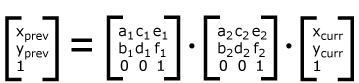
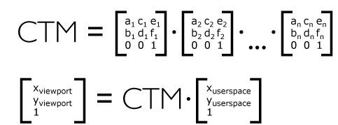
For each given element, the accumulation of all transformations that have been defined on the given element and all of its ancestors up to and including the element that established the current viewport (usually, the ‘svg’ element which is the most immediate ancestor to the given element) is called the current transformation matrix or CTM. The CTM thus represents the mapping of current user coordinates to viewport coordinates:
The SVG definition is straight-forward: the CTM is a post-multiplication of the individual transformation matrices. How does it compare to HTML/CSS? Let’s check the CSS ’transform’ property definition given in CSS Transforms Module Level 1. Remember that this specification was written many years after SVG 1.1, attempting to unify CSS transforms with SVG transforms, providing a single specification that covers both use cases and their interoperability.
CSS Transforms Module Level 1 describes how to compute the transformation matrix from the ’transform’ and ’transform-origin’ properties:
– Start with the identity matrix.
– Translate by the computed X and Y of transform-origin
– Multiply by each of the transform functions in transform property from left to right
– Translate by the negated computed X and Y values of transform-origin
Furthermore it states:
The coordinate space is a coordinate system with two axes: the X axis increases horizontally to the right; the Y axis increases vertically downwards. Transformations are cumulative. That is, elements establish their local coordinate system within the coordinate system of their parent.
From specification point of view, CSS transforms and SVG transforms behave identical, thus we should be able to use the existing code in RenderLayer that handles transformations for SVG as well. However the origin of the transformation matrix differs. Both HTML/CSS and SVG renderers consult the RenderStyle for the transformation matrix if the CSS ’transform’ property is set. If the SVG ’transform’ attribute is set, we can query the SVGTransformList that was parsed from the ’transform’ attribute string in the SVG DOM to fill the transformation matrix.
Different approaches were tested including fully mapping SVG transforms to CSS transforms, by creating CSS transforms from the SVG ’transform’ attribute string. Spinning up the full-fledged CSS parser to parse SVG ’transform’ attributes is slower than the current solution, which keeps the optimized SVGTransformList parsers, whose performance is hard to match with other approaches.
To summarize: there’s a straight-forward recipe to integrate SVG transforms into the places in RenderLayer that currently query only the RenderStyle for the transformation matrix.
6.2. Adapt Layer Tree for RenderSVGModelObject
↑ Table Of ContentsThe RenderLayer / RenderLayerBacking / RenderLayerCompositor classes contain the majority of the Layer Tree implementation. They assume that the RenderLayerModelObject they operate on can be cast to a RenderBox. All these places need to be made aware of RenderSVGModelObject.
Layers are positioned and sized in RenderLayer::updateLayerPosition() – in the RenderBox case the desired size/position of the layer is obtained by calling
RenderBox::frameRect().size() and RenderBox::applyTopLeftLocationOffset(). For these methods, as well as borderBoxRect / visualOverflowRect etc.
SVG equivalents need to be provided in RenderSVGModelObject.
This sounds straight forward on first sight, but there are numerous of details that need to be worked out:
- How to define the
frameRectfor SVG shapes/images/text? - How to define the
frameRectfor SVG containers, that have no intrinsic size? - Do transformations affect the
frameRect? (In HTML they don’t affect layout at all.) - How does it relate to the SVG
objectBoundingBoxorstrokeBoundingBox?
Consider the following SVG document fragment:
<svg xmlns="http://www.w3.org/2000/svg" width="400px" height="400px">
  <rect x="50" y="50" width="100" height="100"/>
</svg>
There is not much freedom here to define the SVG to CSS box model mapping. In the language of CSS, <rect> is a absolutely positioned box, taken out of the normal flow, positioned relative to its nearest positioned ancestor. In the case of a standalone SVG document, that ancestor resolves to the viewport.
Therefore the frameRect (x, y, width, height) is equal to (50, 50, 100, 100). Both the SVG objectBoundingBox and the visualOverflowRect are
identical to the frameRect. The visualOverflowRect will be identical to the frameRect in all following examples, since we won’t specify any
attributes/properties causing visual overflow (such as filters exceeding the content area, etc.), to keep the examples simple.
If the <rect> is transformed, nothing changes. The frameRect / visualOverflowRect / objectBoundingBox all stay the same.
This is consistent with a single HTML <div> both for the transformed and not-transformed case.
Now let’s consider a surrounding container element:
<svg xmlns="http://www.w3.org/2000/svg" width="400px" height="400px">
  <g>
    <rect transform="scale(2)" x="50" y="50" width="100" height="100"/>
  </g>
</svg>
and inspect the geometry:
| objectBoundingBox | frameRect | borderBoxRect | location (x, y) | |
|---|---|---|---|---|
| <svg> | (100, 100, 200, 200) | (0, 0, 400, 400) | (0, 0, 400, 400) | (0, 0) |
| <g> | (100, 100, 200, 200) | (100, 100, 200, 200) | (0, 0, 200, 200) | (100, 100) |
| <rect> | (50, 50, 100, 100) | (50, 50, 100, 100) | (0, 0, 100, 100) | ??? |
The second column is easy to compute, by following the SVG2 object bounding box rules.
Keep in mind that the SVG objectBoundingBox of a container is the union of the children bounding boxes, respecting any transformation applied
on the child elements (the child bounding box is mapped through the child local transformation matrix, before taking the union of all child bounding boxes).
The frameRect / borderBoxRect were computed by using the aforementioned recipe. If we consider both the <g> and the
<rect> element as absolutely positioned box, the layer location for the <g> would be (100, 100) and (50, 50) for the
<rect>, resulting in a layer position for the <rect> of (150, 150). Obviously this simple recipe is not enough
to map SVG to CSS, therefore its not clear yet how to define the last column in the table above (location is what will be returned for applyTopLeftLocationOffset
in the SVG case).
To cut a long story of experimentation and prototyping short, a two-pass approach solves the problem.
Start from RenderSVGRoot and layout all direct descendants. Compute the frameRect (and derived quantities) for each renderer.
When a container element has finished layout, compute its SVG objectBoundingBox and remember the location. Iterate through all direct children
of the container and subtract the container objectBoundingBox.location() from their frameRect location.
This yields the following geometry:
| objectBoundingBox | frameRect | borderBoxRect | location (x, y) | |
|---|---|---|---|---|
| <svg> | (100, 100, 200, 200) | (0, 0, 400, 400) | (0, 0, 400, 400) | (0, 0) |
| <g> | (100, 100, 200, 200) | (100, 100, 200, 200) | (0, 0, 200, 200) | (100, 100) |
| <rect> | (50, 50, 100, 100) | (-50, -50, 100, 100) | (0, 0, 100, 100) | (-50, -50) |
which deserves a closer look.
The <g> element covers the screen from (x, y) = (100, 100) to (x’, y’) = (300, 300). This area is identical to the area that the transformed rectangle covers. The layer for the container element must respect the transformation of the child element for SVG. If a backing store is attached to the RenderLayer for the <g> element (e.g. an image buffer), it needs to be as large as necessary that it can hold an unclipped image of the rendering of the container and its descendants.
Let’s assume the frameRect = (100, 100, 200, 200) for the <g> renderer is correct.
This implies a frameRect = (-50, -50, 100, 100) for the <rect> renderer. A closer
look reveals that this is also correct, since the layer corresponding to the <rect> element is a child layer (in positive z-order list!)
of the layer corresponding to the <g> element. Therefore we end up at (x’, y’) = (100, 100) + (-50, -50) = (50, 50) as location
for the <rect> layer. This corresponds to the nominal location of the renderer, as if no transformation would be applied, which is what we
want to stay compatible with HTML/CSS internally (where the transformations do not affect the layer position).
With this chosen SVG to CSS mapping transformations don’t effect the position of the layer/size itself, but do affect the position and size of the parent layer. This is a novel behaviour, not present in HTML/CSS and reflects the fact that containers in SVG have no intrinsic size but are dynamically sized based on their content and their transformations.
To summarize: a recipe was presented to map SVG layout rules to existing CSS concepts, in such a way that the RenderLayer code can be shared between HTML/CSS and SVG. Instead of only handling RenderBox based renderers, RenderLayer / RenderLayerBacking / etc. additionally need to cope with RenderSVGModelObject.
Finally the layout part of the new layer based painting engine is well defined - let’s move on to painting.
6.3. Painting SVG layers
↑ Table Of ContentsIn a previous section it was discussed how HTML/CSS documents are painted starting from the root layer. When discussing the transformation matrix that gets pushed to the CTM stack, an additional offset – offsetFromParent – was described that gets “right-translated” onto the CSS transformation matrix before the matrix gets pushed onto the CTM stack.
That seems to conflict with SVG, where the CTM is simply the product of all transformation matrices in the ancestor
chain. In RenderLayer::paintLayerByApplyingTransform() clearly an additional transformation is injected in the CTM stack.
Unless these offsets are zero, that would be in conflict with SVGs definition of the CTM.
Furthermore CSS Transforms Module Level 1 does not explicitly describe the offsetFromParent translation. So, what is the role of this offset?
As this is an important point, let’s construct an example of two CSS boxes that are painted in the same location, but one is additionally scaled:
<!DOCTYPE html>
<html>
  <head>
    <style>
      body {
          margin: 10px;
      }

      .container {
          position: absolute;
          background-color: blue;
          width: 300px;
          height: 300px;
      }

      .box {
          position: absolute;
          width: 100px;
          height: 100px;
          left: 50px;
          top: 50px;
      }

      .box-no-trafo {
          background-color: green;
      }

      .box-trafo {
          background-color: red;
          transform: scale(2);
          transform-origin: 0 0;
      }
    </style>
  </head>
  <body>
    <div class="container">
      <div class="box-trafo box"></div>
      <div class="box-no-trafo box"></div>
    </div>
  </body>
</html>
Output:
From the Render Tree dump
(B)lock/(I)nline/I(N)line-block, (A)bsolute/Fi(X)ed/(R)elative/Stic(K)y, (F)loating, (O)verflow clip, Anon(Y)mous, (G)enerated, has(L)ayer, hasLayer(S)crollableArea, (C)omposited, (+)Dirty style, (+)Dirty layout
B---YGLSC --  RenderView at (0,0) size 1440x742 renderer->(0x145f31380)
B-----LS- --*   HTML RenderBlock at (0,0) size 1440x10 renderer->(0x145f31c50) node->(0x145f31aa0)
B-------- --      BODY RenderBody at (10,10) size 1420x0 renderer->(0x145f31d80) node->(0x145f31bc0)
BA----L-- --        DIV RenderBlock at (10,10) size 300x300 renderer->(0x145f334f0) node->(0x145f331f0)
BA----L-- --          DIV RenderBlock at (50,50) size 100x100 renderer->(0x145f33620) node->(0x145f332f0)
BA----L-- --          DIV RenderBlock at (50,50) size 100x100 renderer->(0x145f33750) node->(0x145f333f0)
there is no difference between the two last <div> elements. Same for the Layer Tree dump:
layer 0x145ad50a0 scrollableArea 0x145ad32a0 at (0,0) size 1440x742 (composited [root], bounds=at (0,0) size 1440x742, drawsContent=1, paints into ancestor=0)
  RenderView 0x145f31380 at (0,0) size 1440x742
 positive z-order list (1)
  layer 0x145ad51d0 scrollableArea 0x145ad2880 at (0,0) size 1440x10
    RenderBlock 0x145f31c50 {HTML} at (0,0) size 1440x10
      RenderBody 0x145f31d80 {BODY} at (10,10) size 1420x0
   positive z-order list (3)
    layer 0x145ad5300 at (10,10) size 300x300
      RenderBlock (positioned) 0x145f334f0 {DIV} at (10,10) size 300x300 [bgcolor=#0000FF] class="container"
    layer 0x145ad5430 at (60,60) size 100x100
      RenderBlock (positioned) 0x145f33620 {DIV} at (50,50) size 100x100 [bgcolor=#FF0000] class="box-trafo box"
    layer 0x145ad5560 at (60,60) size 100x100
      RenderBlock (positioned) 0x145f33750 {DIV} at (50,50) size 100x100 [bgcolor=#008000] class="box-no-trafo box"
All three <div> elements are absolutely positioned. The outer <div> element is 300px x 300px wide and located at (x=10px, y=10px). The inner <div> elements are both reported to paint at (x=60px, y=60px) with a size of 100px x 100px, each. This is aligned with the CSS transforms specification:
Note: Transformations do affect the visual rendering, but have no affect on the CSS layout other than affecting overflow.
From the Render Tree and Layer Tree dumps one cannot deduce the role of the additional transformation offsetFromParent.
The easiest way to trace this is to run the example in MiniBrowser and break on RenderBlock::paint. Now we can examine the
location(), as well as the external paintOffset, passed from the RenderLayer that triggered
the RenderBlock::paint() call.
| element | paintOffset (x, y) | location (x, y) | paintOffset + location |
|---|---|---|---|
| html | (0, 0) | (0, 0) | (0, 0) |
| body | (0, 0) | (10, 10) | (10, 10) |
| div “container” | (0, 0) | (10, 10) | (10, 10) |
| div “box-trafo” | (-50, -50) | (50, 50) | (0, 0) |
| div “box-no-trafo” | (10, 10) | (50, 50) | (60, 60) |
The paintOffset for the transformed CSS box is (-50, -50) as opposed to (10, 10) (no transformation). Therefore the adjustedPaintOffset = paintOffset + location is defined to be (0, 0) for transformed boxes.
The paintOffset is computed in the various RenderLayer::paintXXXForFragments() methods, that are called
from RenderLayer::paintLayerContents() and is equal to:
fragment.layerBounds.location() - renderBoxLocation() + localPaintinginfo.subpixelOffset
For unpaginated layers there’s only one “fragment” describing the whole RenderLayer.
The fragment.layerBounds.location() is equal to the offset from the nearest transformed ancestor with respect to the rootLayer
stored in the LayerPaintingInfo data structure (offsetFromAncestor()).
The following table shows the offsetFromParent quantity for all layers:
| layer for element | Transform | offsetFromParent | layerBounds | paintOffset |
|---|---|---|---|---|
| html | identity | (0, 0) | (0, 0, 1440, 10) | (0, 0) |
| div “container” | identity | (10, 10) | (10, 10, 300, 300) | (0, 0) |
| div “box-trafo” | “scale(2)” | (0, 0) | (0, 0, 100, 100) | (-50, -50) |
| div “box-no-trafo” | identity | (60, 60) | (60, 60, 100, 100) | (10, 10) |
The scaled CSS box has offsetFromParent set to (0, 0) instead of the nominal (60, 60), thus leading
to the paintOffset of (-50, -50). Note that offsetFromParent for the scaled CSS box was actually
equal to (60, 60), until RenderLayer::paintLayerByApplyingTransform() got called. At this point the
(60, 60) translation got encoded into the CTM (right-translation of offsetFromParent = (60, 60)).
Also rootLayer in LayerPaintingInfo now points to this. The next call to offsetFromAncestor(rootLayer)
will now return zero, instead of (60, 60). This is all consistent, just somewhat convoluted on first sight.
The role of the additional offestFromParent translation, injected by RenderLayer::paintLayerByApplyingTransform()
should be clear now: It encodes the effective position of the renderer - that’s usually passed via paintOffset
from the layer to the renderer - in the CTM.
CSS Transforms Module Level 1 actually describes this transformation implicitly here:
In general, a coordinate system defines locations and distances on the current canvas. The current local coordinate system (also user coordinate system) is the coordinate system that is currently active and which is used to define how coordinates and lengths are located and computed, respectively, on the current canvas.
Furthermore:
The current user coordinate system has its origin at the top-left of a reference box specified by the transform-box property. Percentage values are relative to the dimension of this reference box. One unit equals one CSS pixel.
The initial value of the CSS ’transform-box’ property equals to view-box - which means: use the nearest SVG viewport as reference box.
For elements with associated CSS layout box, the used value for view-box is border-box. Therefore the transformations in our example
shall be applied in a coordinate system, where the top-left origin is equal to the location of the top-left edge of the border-box.
Thus we have to translate to the offsetFromParent origin, before applying the CSS transformation - which is exactly what’s implemented
in RenderLayer::paintLayerByApplyingTransform(). All ’transform-box’ values require the same initial translation to the offsetFromParent.
For SVG, the default view-box ’transform-box’ indicates that the transformation should be applied in a coordinate system where the top-left origin is equal to the location of the top-left edge of the SVG viewPort. The translation to the offsetFromParent thus is superfluous in the SVG context for the default ’transform-box’ mode.
Thus it’s tempting to simply omit the translation for SVG. However that will break the world, since RenderLayer / RenderLayerBacking are
implicitly relying on the assumption that the top-left origin of a transformed layer is equal to the top-left edge of the CSS border box,
after RenderLayer::paintLayerByApplyingTransform() was called. In an earlier version of the PoC this design was tried – it works,
but leads to additional coordinate system translations in various places. It works, but it’s inconvenient.
An elegant solution to the problem is to teach RenderLayer about a SVG specific painting mode, only used for SVG renderers.
First translate by T1, apply the CSS transformation T2 and translate by T3. T2 always corresponds to the CSS ’transform’ property
set on the renderer or the SVG ’transform’ attribute. T3 corresponds to offsetFromParent plus the objectBoundingBox.location() of the root layer
corresponding to the <svg> renderer (the additive term vanishes in standalone SVG document, but is relevant for inline SVG in HTML content).
T1 is equal to identity when encountering the first transformed SVG layer and identical to the inverse T3 of the last transformed SVG layer in the
ancestor chain, for any child of a transformed SVG layer.
This sounds complex, let’s look at a concrete example: When rendering the <g> element in the example above, RenderLayer::paintLayerByApplyingTransform()
detects a SVG renderer and translates to T3 = (100, 100). That’s all – there are no transformations T2 specified on the <g> element, and no previous
transformed SVG layer, thus T1 is identity.
Afterwards the <rect> element is rendered: we first translate by T1 = (-100, -100), then apply the T2 = “scale(2)” transformation and finally translate by T3 = (50, 50). The net effect is that the CTM is equal to the product of the individual transformation matrices of the ancestor chain plus a single translation in the end that moves the coordinate system to the top-left edge of the SVG renderer. The coordinate system is now prepared in a way, that the RenderLayer assumptions all hold true and that all SVG transformation requirements are fulfilled. Mission completed: we can now layout and paint layers in the layer based SVG engine!
Hit-testing is intentionally left out here – the document is already lengthy. Take my word on this, that the whole RenderLayer hit-testing code can be re-used as-is, with only minimal modifications in two places that utilize offsetFromAncestor.
Let’s now focus on the patch that implements the layer based SVG engine and discuss the next steps.